Programming a lie detector on the Arduino Uno board
Repository
https://github.com/arduino/arduino
What Will I Learn?
- Function of a lie detector
- Application of a real system with Arduino Uno.
- Programming with Arduino Uno.
Requirements
- Operation of the Arduino Uno card.
- Standard programming for Arduino.
- Knowledge of acquisition of physiological signals.
Difficulty
- Intermediate
Tutorial Contents
Greetings, this tutorial is a contribution for Utopian-io of the @gasuba account. The lie detector is based on the polygraph principle, which detects the galvanic response or conductance of the skin, which translates skin variations when a person is interrogated and tries to tell a lie. In this sense when a person says a lie decreases their skin resistance.
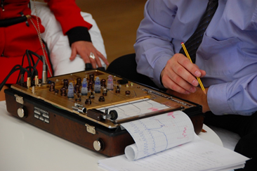
The working principle of the polygraph to be used is shown in the following image. For this project the Arduino Uno card will be used, which we will proceed to program taking into account the respective considerations:
- A reference point based on a tension point will be established, which will serve as a point of comparison with the value obtained from the metal plate, whose perturbations will depend on the response of the person to be interrogated. This will help us structure the programming.
- By decreasing the cutaneous resistance, it implies that the person is lying and, therefore, the analog input of the Arduino (AO) will tend to 5V and this will activate an output of the system.
- The greater the cutaneous resistance, implies that the person is telling the truth and, therefore, the analog input of the Arduino (AO) will tend to 0 V and this will activate an output of the system.
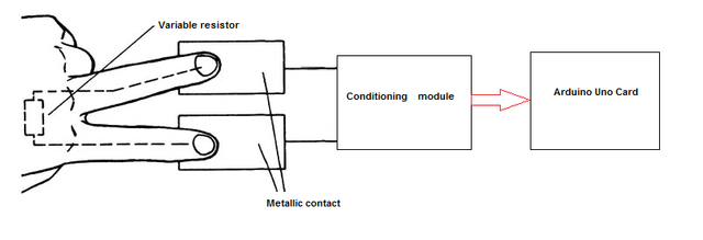
Own Source
Outputs to use from the Arduino:
Indicators of light and an alarm in the output of the Arduino that corresponds to pins 6,7,8 and 9 to indicate:
- Blue color: the person questioned tells the truth.
- Green color: reference point.
- Red color: the respondent lies and an alarm is generated
Below are some code segments that will help the reader to program the Arduino card:
Segment 1:
Declaration of ports where the outputs and inputs of the Arduino will be found, being of an integer and floating type, the latter for the case of analog inputs:
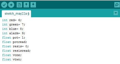
Segment 2:
Configuration of the ports that will be outputs on the Arduino, for this we use the pinMode () command and perform it within the void setup () cycle, to use the serial monitor, the transmission speed is with the Serial command Serial.begin ():
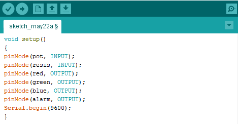
Segment 3:
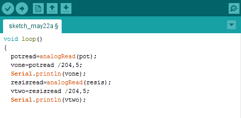
We start the cycle of void loop () to establish the conditions of the design based on the programming of the Arduino card. Taking into account that you want to establish a range of 0 to 5V, proceed to divide the analogous value read in the two pins between 204.5 and with the Serial.println () command, print the values in the serial monitor with the purpose to observe the variation of the values generated in the AO pin:
Segment 4
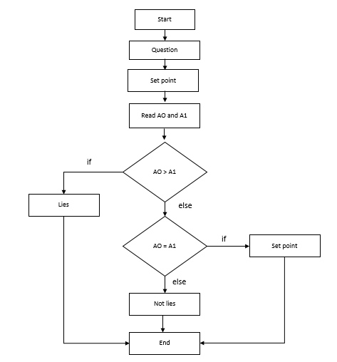
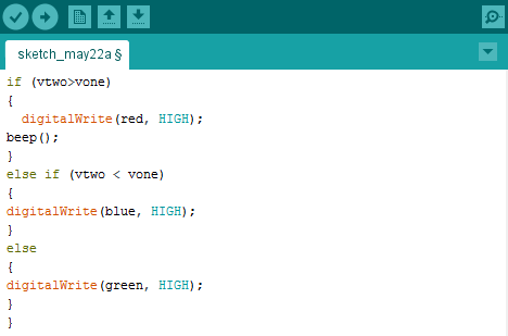
Once the reference value is established, we make a comparison between this value (vone) and the value of vtwo, establishing two conditions see down the flow diagram and the programming structure:
- If the vtwo value is less than vone, turn on blue light.
- If the vtwo value is higher than vone, turn on the red light and turn on the alarm (beep).
- If none of the previous ones is turned on, turn on the green light.
We close the cycle void loop ().
Own Source
Segment 5
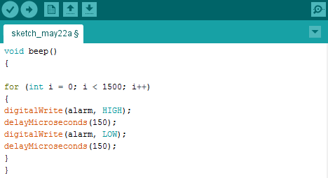
In segment 4 the beep () function appears, whose function corresponds to the configuration of the alarm, in terms of the time it generates the sound pulses (150us), then the programming:
Segment 6
To perform the tests with the lie detector, you must give instructions to the person to be interrogated. Placing the fingers on the metal plates and convincing the interrogated that the device works.
It is worth mentioning that the reference point is used in the conditioning module before the Arduino and a potentiometer can be suggested. Therefore, each time the system changes from green light to red or blue light, it must readjust with the reference point again to the green light and continue with the interrogation. This for each question.
Segment 7
An illustration about the components to use if you want to check the real system:

Own Source
Thanks for your time and attention...!!!!
Thank you for your contribution.
Kindly note the following notes and suggestions for your future work:
Your contribution has been evaluated according to Utopian rules and guidelines, as well as a predefined set of questions pertaining to the category.
To view those questions and the relevant answers related to your post,Click here
Need help? Write a ticket on https://support.utopian.io/.
Chat with us on Discord.
[utopian-moderator]
Congratulations! This post has been upvoted from the communal account, @minnowsupport, by gasuba from the Minnow Support Project. It's a witness project run by aggroed, ausbitbank, teamsteem, theprophet0, someguy123, neoxian, followbtcnews, and netuoso. The goal is to help Steemit grow by supporting Minnows. Please find us at the Peace, Abundance, and Liberty Network (PALnet) Discord Channel. It's a completely public and open space to all members of the Steemit community who voluntarily choose to be there.
If you would like to delegate to the Minnow Support Project you can do so by clicking on the following links: 50SP, 100SP, 250SP, 500SP, 1000SP, 5000SP.
Be sure to leave at least 50SP undelegated on your account.