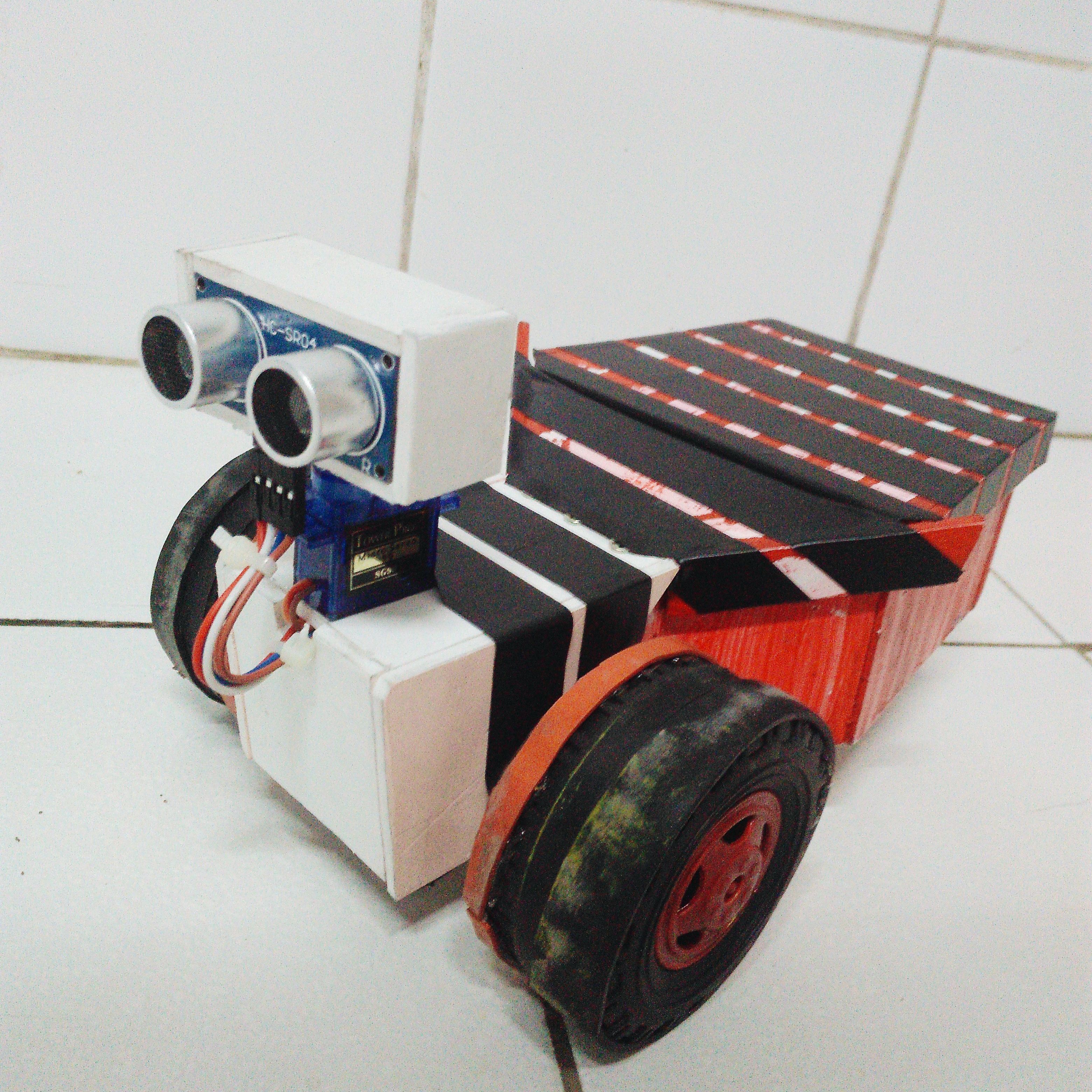
THE MAKING OF IKE2.0 ROBOT: A Collision-Avoidance Robot
Greetings Fellows!
In line with our Robotics subject, our instructor tasked us to make two robots as our project for the whole sem. The one which I posted a month ago which is the LINE-FOLLOWING Robot and now the COLLISION-AVOIDANCE Robot.
WHAT IS A COLLISION-AVOIDANCE ROBOT?
The collision- avoidance robot is used for detecting obstacles and avoiding collision. This is an autonomous robot which requires the integration of many sensors according to their task.
WHAT IS ITS PRINCIPLE OF OPERATION?
Avoiding collision is the primary requirement of this autonomous robot. The robot gets the information from surrounding area through mounted sensors on it. Some sensing devices used for obstacle detection like bump sensor, infrared sensor, ultrasonic sensor etc. Ultrasonic sensor is most suitable for obstacle detection and it is of low cost and has high ranging capability.
WHAT ARE THE MAIN COMPONENTS USED?
1.ULTRASONIC SENSOR
OPERATION:
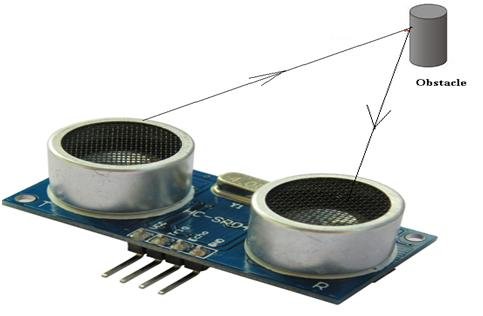
An Ultrasonic sensor is a device that can measure the distance to an object by using sound waves. It measures distance by sending out a sound wave at a specific frequency and listening for that sound wave to bounce back
2.SERVO MOTOR
A servomotor is a rotary actuator or linear actuator that allows for precise control of angular or linear position, velocity and acceleration. It consists of a suitable motor coupled to a sensor for position feedback.
3.ARDUINO UNO- Main Microcontroller
Arduino Uno is a microcontroller board based on the ATmega328P (datasheet). It has 14 digital input/output pins (of which 6 can be used as PWM outputs), 6 analog inputs, a 16 MHz quartz crystal, a USB connection, a power jack, an ICSP header and a reset button.
THE MAKING OF THIS ROBOT
Since, I already did a robot which is the LINE-FOLLOWING Robot and the casing was already made, some additional features with regards to its functionality were integrated into this second robot. And for you to be able to understand more, I will display the difference between the two robots I made.
| Name of Robot | Microcontroller | # of Servomotors |
|---|---|---|
| Line-Following | ArduinoUNO | 2 |
| Collision-Avoidance | ArduinoUNO | 3 |
MORE TO UNDERSTAND:
The making of this Collision-Avoidance robot requires 3 Servomotors and since I already have 2 when I made my Line-Following Robot, there's 1 still needed.
How can this one Servomotor be used?
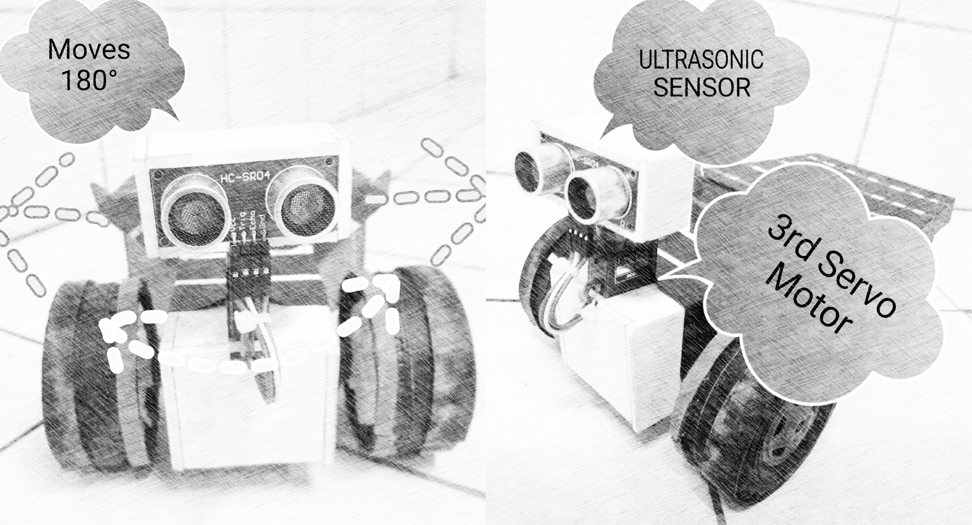
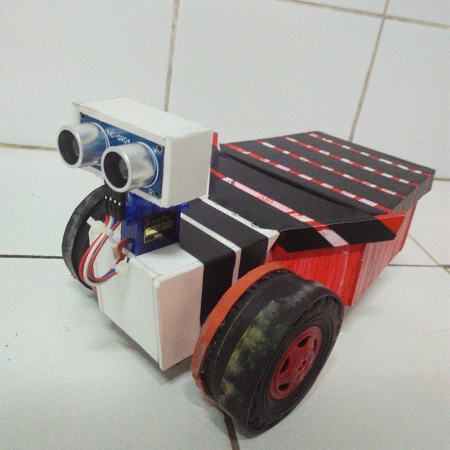
Simply, the 3rd Servomotor is used to attach the Ultrasonic sensor above it so that the sensor can just easily rotate to all directions as in 180 degrees. When the sensor senses that there is an obstacle in front, the robot would stop and for a moment the Servomotor with the sensor would rotate to locate a direction where there is no obstacle and then it would pass through.
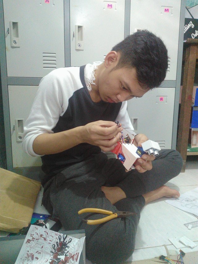
The following are the photos and steps that were taken during the making of this robot.
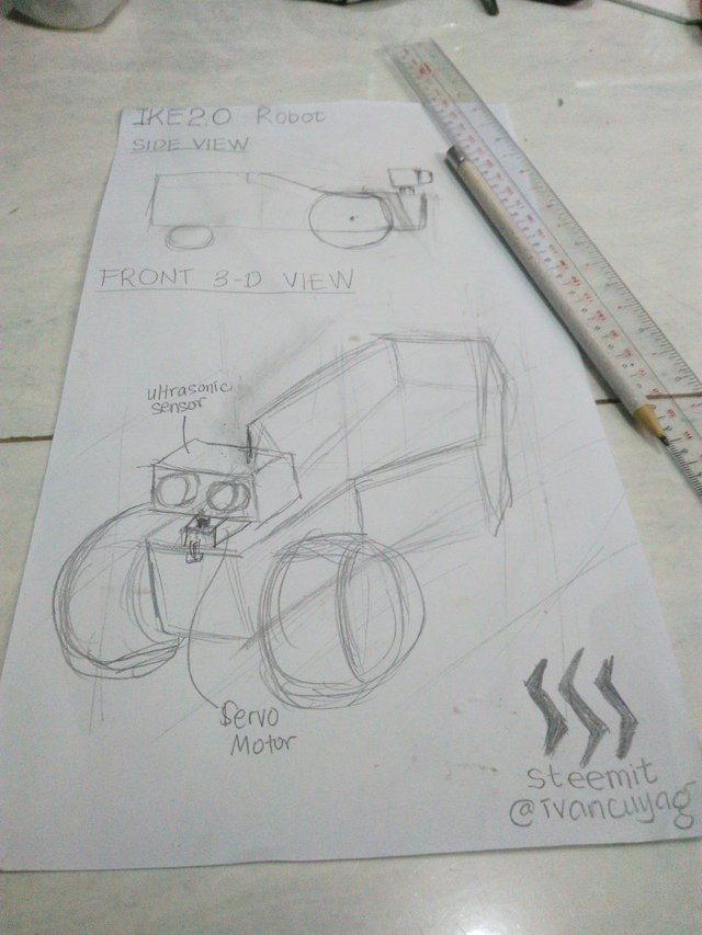
1.Make a sketch about the robot's additional features.
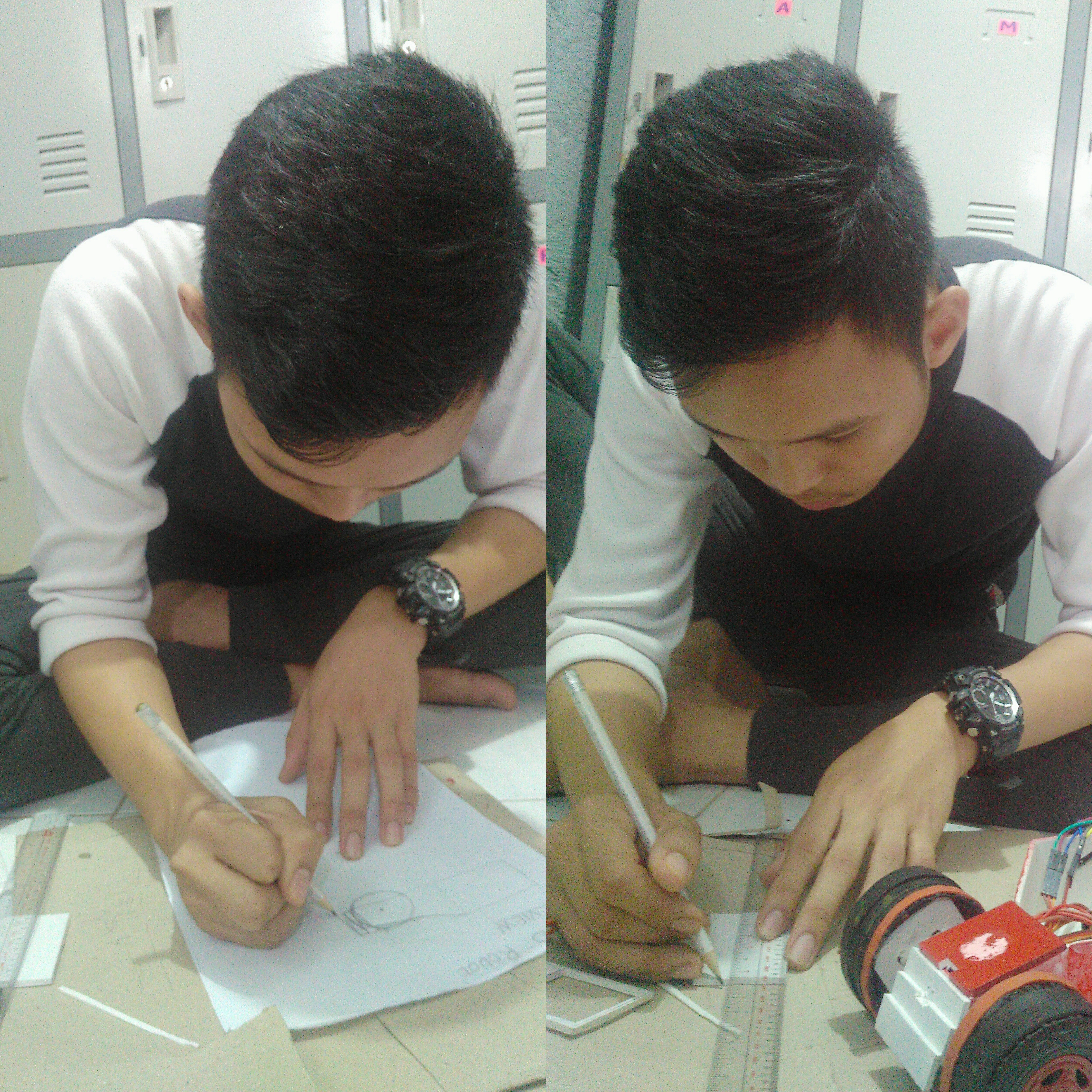
2.Build and screw it at the front portion.

FUNCTIONALITY:
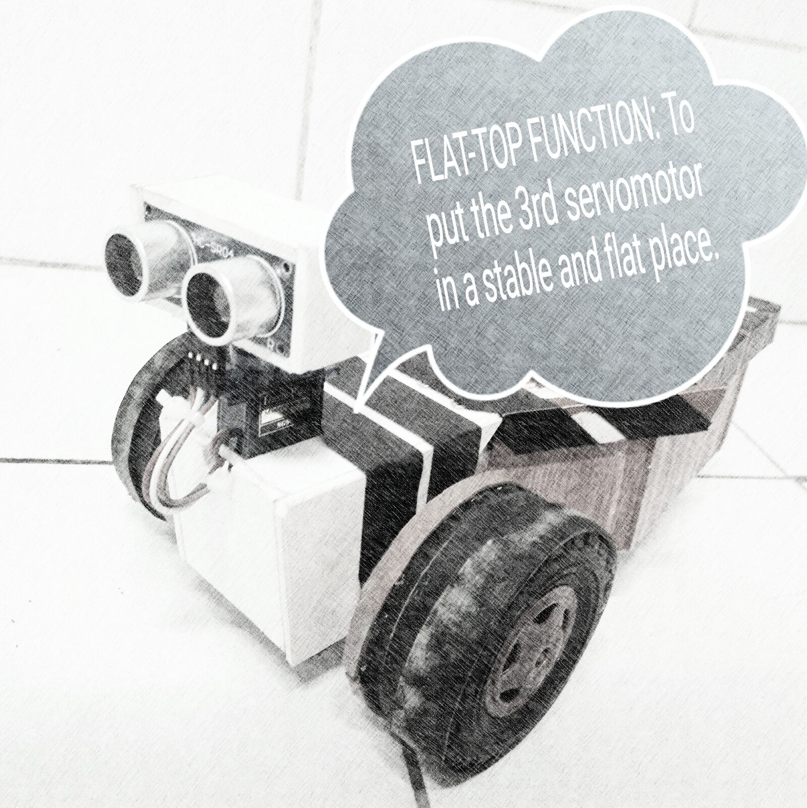
P.S. I added a flat top along the front so I could easily mount the third Servo motor to be placed at the front. This is actually the component which can drive the ULTRASONIC Sensor.
3.Make a box for the Ultrasonic sensor which could serve as an eye for the robot.

And this is how it goes:
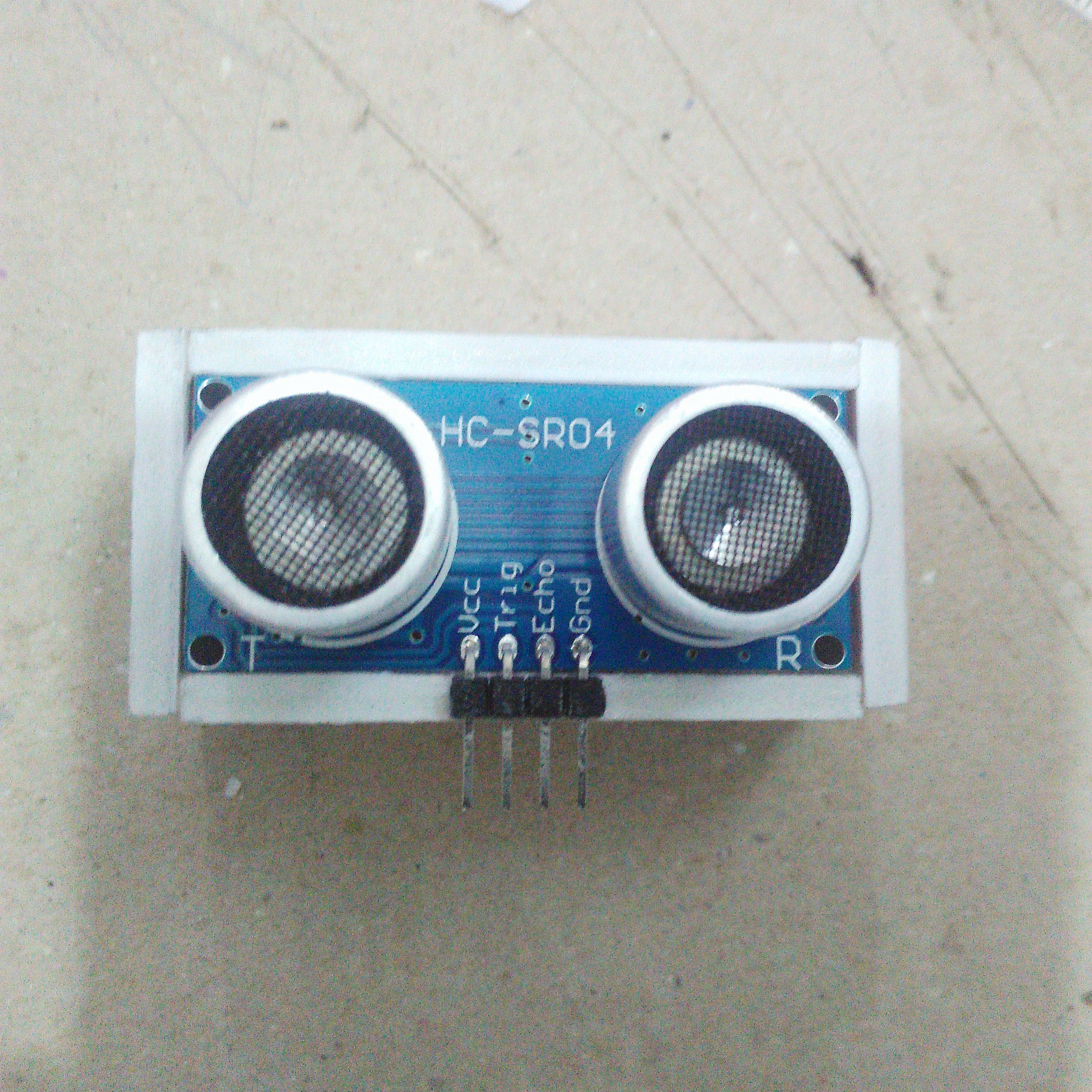
4.Attach the box onto the chassis.
And there you have it, partially,
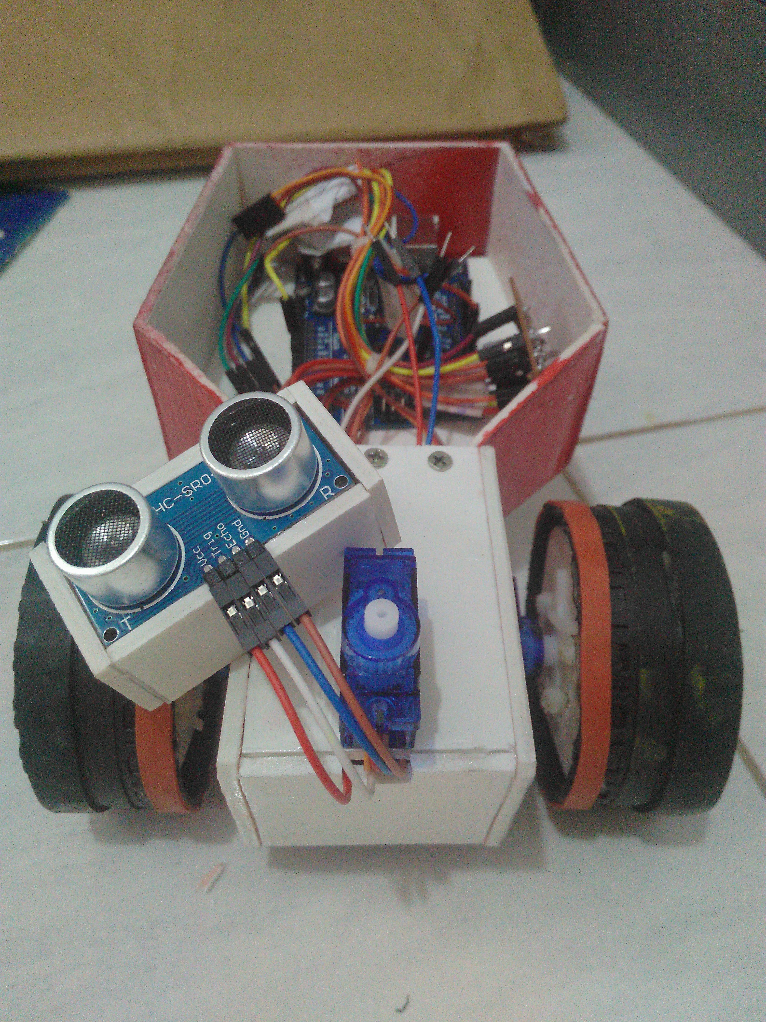
And completely,
5.Make the program codes.
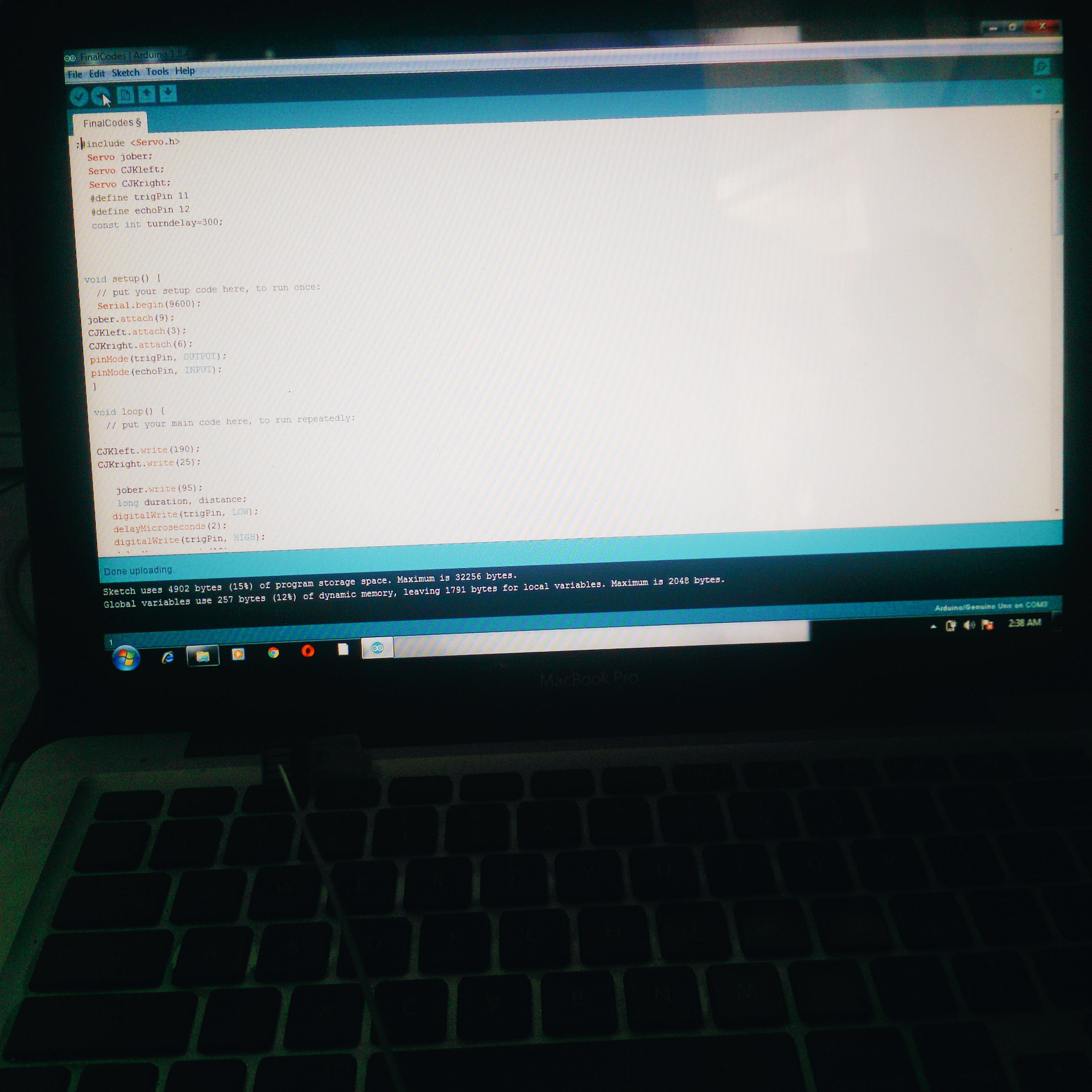
HERE IS THE PROGRAM:
#include <Servo.h>
#include<NewPing.h>

#define echoPin 8
#define trigPin 9
#define maxrange 200

Servo servoLeft;
Servo servoRight;
Servo servoScan;
const int stoprange = 10;

NewPing sonar(trigPin, echoPin, maxrange);

unsigned int duration;
unsigned int distance;
unsigned int FrontDistance;
unsigned int LeftDistance;
unsigned int RightDistance;
unsigned int Time;
unsigned int CollisionCounter;

void setup()
{
  Serial.begin (115200);
  servoLeft.attach(3);
  servoRight.attach(4);
  servoScan.attach(6);
}

void loop()
{
  servoScan.write(90);
  scan();
  FrontDistance = distance;
  Serial.print("Front Distance = ");
  Serial.print(distance);

  if (FrontDistance > 25 || FrontDistance == 0)
  {
    go();
  }
  else
  {
    CollisionCounter = CollisionCounter +1;
    stopmotor();
    navigate();
  }
}

void go()
{
  servoLeft.write(180);
  servoRight.write(0);
}

void turnLeft()
{
  servoLeft.write(180);
  servoRight.write(180);
  delay(300);
}
void turnRight()
{
  servoLeft.write(0);
  servoRight.write(0);
  delay(300);
}

void stopmotor()
{
  servoLeft.write(110);
  servoRight.write(110);
}

void reverse()
{
  servoLeft.write(0);
  servoRight.write(180);
  delay(200);
}

void scan()
{
  Serial.println("");
  Serial.println("Scanning");
  Time = sonar.ping();
  distance = Time / 58.2;
  delay(100);
}

void navigate()
{
  Serial.println(" There's an Obstacle!");
  servoScan.write(180);
  delay(300);
  scan();
  LeftDistance = distance;
  Serial.print("Left distance = ");
  Serial.print(distance);

  servoScan.write(0);
  delay(300);
  scan();
  RightDistance = distance;
  Serial.print("Right distance = ");
  Serial.print(distance);

  servoScan.write(90);
  delay(100);

  if(abs(RightDistance - LeftDistance)<5)
  {
    turnRight();
  }

  else if(RightDistance<LeftDistance)
  {
    reverse();
    turnRight();
  }

  else if(LeftDistance<RightDistance)
  {
    reverse();
    turnLeft();
  }
}
This actually took time since you have to perform trial-and-error method to precisely set the angle for the third servo motor.
And yes! The final product:

BUT WAIT THERE'S MORE!
TO REALLY PROVE IT TO YOU GUYS, HERE IS THE COMPLETE RUN OF THIS ROBOT:
P.S. You may wonder what the green thing above the robot but it's actually a powerbank- the supply voltage for the microcontroller for the robot to function.
And that's it! I hope you guys like this post and also hoping that you get some insights out from this project as well. For more Electronic project to be posted soon just keep updated. Thank you so much for dropping by. Forget not to upvote and follow Steemians!
As always with love and passion to share,
IVAN 📷📡


Can I suggest add source links or give credit for the source for the italicize words?
Yeah! That's right. I forgot to put. Anyways nect time Ill do it. Thanks anyhow @cyres. God bless you. K
Impressive.
Mabuhay! Your post has been upvoted and resteemed by the @bayanihan curation team.
viewed, voted, commented, and re-steemed ...
anyone follows me i'll follow back within a few days
Thanks :)
Galing! congrats!
Salamat pari!
Congratulations @ivancuyag! You have completed some achievement on Steemit and have been rewarded with new badge(s) :
Click on any badge to view your own Board of Honor on SteemitBoard.
For more information about SteemitBoard, click here
If you no longer want to receive notifications, reply to this comment with the word
STOPGaling naman. :)
Thanks po
liked your post great post dear.....hope u like my post too.....
Thank you.
Wow nice project tho
Wow, great work