A Comprehensive Guide to Electronic Load for Modern Power Testing
Introduction
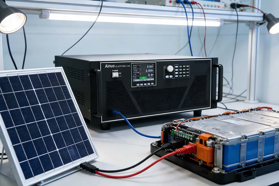
In the world of power electronics testing and validation, the electronic load stands as one of the most indispensable instruments in any engineer's toolkit. Whether you are designing a bench power supply, validating a battery management system, or stress-testing a DC-DC converter, an electronic load provides the controllable, repeatable, and precisely measurable sink for electrical energy that manual resistive loads simply cannot match.
This guide explores what an electronic load is, how it works, the different operating modes it supports, and how to select the right unit for your specific application.
What Is an Electronic Load?
An electronic load is a test instrument that simulates an electrical load by absorbing and dissipating electrical power from a device under test (DUT). Unlike passive resistive loads — which are fixed resistors that convert electrical energy into heat — an electronic load uses active semiconductor components (typically power MOSFETs or IGBTs) controlled by precision feedback circuits to replicate virtually any load condition on demand.
The key advantage is programmability: you can set the exact current, resistance, power, or voltage that the load presents to the DUT, and most modern units allow you to sweep through load profiles, simulate transient events, and log measurement data — all from a front panel or remote interface.
Electronic loads are available in both DC and AC variants:
- DC Electronic Loads are used for batteries, DC power supplies, fuel cells, solar panels, and DC-DC converters.
- AC Electronic Loads handle AC power sources, UPS systems, and AC-DC power supplies.
How Does an Electronic Load Work?
At its core, an electronic load is a variable current sink. The main power stage consists of one or more power transistors connected between the input terminals. A control loop monitors the actual current (or voltage, or power) and continuously adjusts the gate drive of the transistors to maintain the desired setpoint.
Here is a simplified operational flow:
- Setpoint Entry – The user programs a desired load condition (e.g., 5 A constant current).
- Sensing – High-precision current and voltage sensors monitor the actual DUT output.
- Error Amplification – The difference between the setpoint and the actual measured value is amplified.
- Gate Drive Adjustment – The control loop drives the power MOSFET(s) to minimize the error.
- Thermal Dissipation – The absorbed power is converted to heat and removed via heatsinks and fans.
Modern electronic loads achieve this regulation at bandwidths from DC up to several hundred kHz, enabling them to emulate dynamic loads such as switching regulators, motor drives, or communication equipment.
Key Operating Modes
A professional electronic load typically supports four fundamental operating modes:
1. Constant Current (CC) Mode
The load maintains a fixed current draw regardless of the DUT's output voltage. This is the most commonly used mode for battery discharge testing, current limiting evaluation, and power supply load regulation tests.
Typical use case: Discharging a lithium-ion battery pack at a constant 10 A to measure capacity.
2. Constant Voltage (CV) Mode
The load regulates its terminal voltage to a fixed value by drawing whatever current is necessary. This mode is useful for testing the source impedance of power supplies.
Typical use case: Testing the dynamic response of a power supply when the load demands voltage clamping.
3. Constant Resistance (CR) Mode
The load presents a fixed ohmic resistance to the DUT. The current drawn is proportional to the input voltage (I = V/R). This mode emulates a real resistive load.
Typical use case: Simulating a heating element or resistive end-device.
4. Constant Power (CP) Mode
The load absorbs a fixed amount of power regardless of voltage or current. As voltage rises, current drops proportionally, and vice versa.
Typical use case: Simulating a regulated switching power supply as a load, which typically draws constant power.
Advanced Features of Modern Electronic Loads
Beyond the four basic modes, high-end electronic loads offer a wealth of advanced capabilities:
Dynamic Mode / Transient Testing
This allows the load to switch rapidly between two load levels at a programmable frequency and duty cycle. It is critical for testing power supply transient response — how quickly and accurately the supply recovers from a sudden change in load current.
Short-Circuit Simulation
The load can simulate a brief short circuit across the DUT output, which is essential for validating overcurrent protection (OCP) circuits.
Battery Simulation and Battery Testing
Some advanced units can simulate the internal resistance model of a battery, enabling back-to-back testing of charger/battery systems. Conversely, they can fully discharge a battery under controlled conditions to measure capacity and characterize aging.
Waveform-Based Loading
Top-tier electronic loads accept arbitrary load waveforms (e.g., sinusoidal, pulsed, or custom profiles stored in memory), enabling realistic simulation of loads like motor drives or telecommunications equipment.
Data Logging and Analysis
Integrated data logging with timestamped V/I measurements makes it easy to capture charge/discharge curves, efficiency maps, and regulation plots without external instruments.
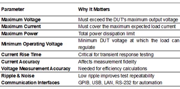
Key Specifications to Evaluate
When selecting an electronic load, pay attention to these specifications:
Common Applications
Electronic loads are found across a wide range of industries and use cases:
- Power Supply Manufacturing – End-of-line testing of AC-DC and DC-DC converters
- Battery R&D – Capacity testing, cycle life evaluation, and internal resistance measurement
- Automotive Electronics – Validating EV battery management systems, DC charging systems, and onboard chargers
- Renewable Energy – Testing solar charge controllers and fuel cell regulators
- Telecommunications – Qualifying 48 V server power systems and base station power supplies
- Aerospace & Defense – Environmental stress screening of ruggedized power converters
Choosing Between Single-Channel and Multi-Channel Units
Single-channel electronic loads are the most common and cost-effective choice for benchtop use. They handle one DUT at a time and are ideal for R&D labs and low-volume production testing.
Multi-channel or modular electronic loads place multiple independent channels in a single mainframe. This is the preferred architecture for:
- High-throughput production test systems
- Multi-output power supply validation
- Parallel cell or module testing in battery research
Modular systems from vendors such as Chroma, Keysight, and Kikusui allow mixing channel ratings within a single chassis, providing maximum flexibility.
Safety Considerations
Working with electronic loads demands respect for electrical safety:
- Polarity Protection – Never reverse-connect the DUT; many loads have protection diodes, but damage can still occur.
- Overvoltage Protection – Ensure the DUT voltage never exceeds the load's rated input voltage.
- Thermal Management – Verify adequate airflow around the unit; high-power dissipation requires forced cooling.
- Grounding – Properly ground both the load chassis and the DUT to prevent ground loops and measurement errors.
- Remote Sense – Use the remote sense terminals when cable resistance would otherwise cause a significant voltage drop.
Conclusion
The electronic load is a cornerstone of modern power electronics testing. Its ability to precisely simulate any desired load condition — across constant current, constant voltage, constant resistance, and constant power modes — makes it invaluable from the earliest stages of product design through final production testing and field qualification.
As power systems grow more complex, with higher voltages, higher currents, faster transients, and tighter efficiency mandates, the demands on electronic loads continue to escalate. Investing in a high-quality, feature-rich electronic load is not merely a convenience — it is a prerequisite for rigorous, reproducible power testing in today's competitive landscape.
Whether you are a seasoned power electronics engineer or just beginning your journey into test and measurement, understanding the capabilities and operating principles of the electronic load is essential knowledge that will serve you throughout your career.