Laptop - Part Two
I've been using the laptop regularly, so it was time to make some changes. Some of those changes are in software for a nicer UI and some of those are in hardware, namely, a bigger screen. The software changes will be the content for a new post, I'm going to show some of the hardware stuff here.
The small screen was fine for regular writing, but for web browsing and the few simple games I play it was a little too small. Not to mention image editing for steemit posts.
The Screen
I found a bigger screen on Amazon, it's the 13.3 inch Elecrow display (note: the product is no longer available, a much more expensive version is now.) It came in a few different flavors, I picked one that was a monitor with with two HDMI inputs, (which I found were actually HDMI mini, which was a problem, but we'll get into that later,) built-in speakers, and the ability to take power via either a barrel jack adapter or USB.
The bigger screen prompted the next few changes, because I really can't risk it being free-floating in my laptop case.
If you recall from my last laptop related post, I'm using a Vaultz clipboard locking case as my laptop housing. It has an internal width of twelve inches and an internal height of nine and three quarter inches. The new screen housing was roughly twelve and a quarter inches wide. So I had to remove it from the housing to fit it into the laptop. That was really too bad, the housing it came in was nice and sturdy. It was also really easy to take apart, just some screws to remove and some fabric tape to peel off the back of the LCD.
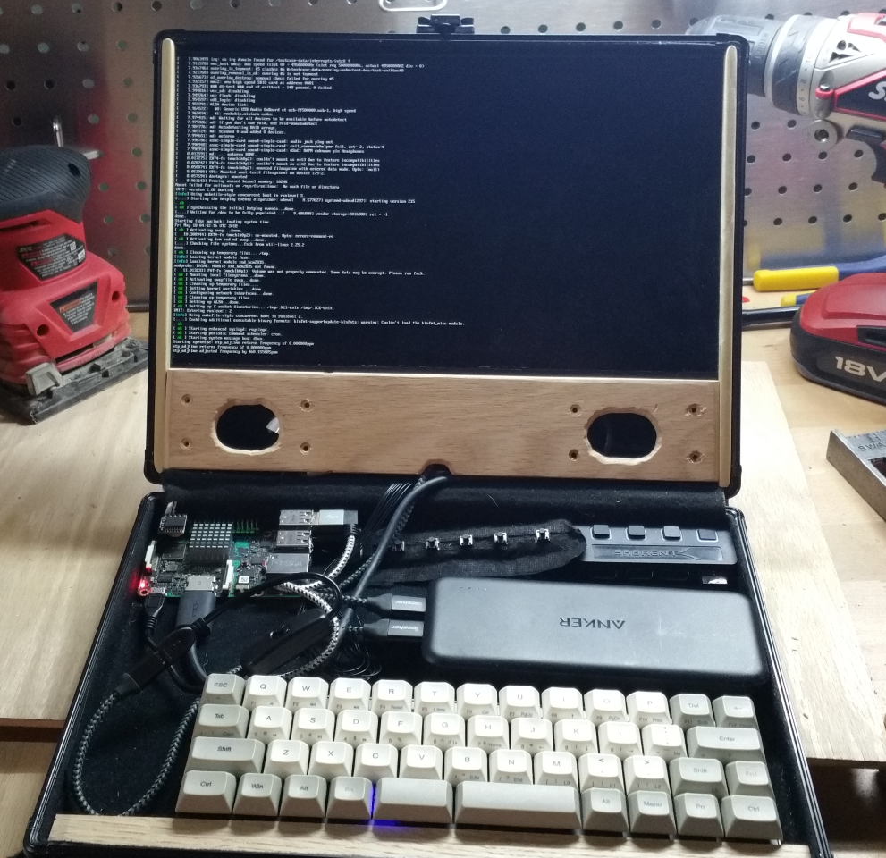
I removed the screen from its housing and laid it into the laptop case. It had about an eight of an inch of leeway on the sides, and about an inch and three quarters room between the bottom of the screen and the bottom of the lid. For a while I left it free floating while I worked on figuring out where I was going to mount the LCD controller board. I discovered that the HDMI ports were actually mini HDMI. This was a problem because it meant I needed room for the adapter and an HDMI cable next to the board. While I could have otherwise mounted this board right behind the display and not taken up any extra room in my case, the adapter meant there wasn't going to be any room to do that in the lid. So, I ended up keeping the controller board in the bottom of the case and ran just the ribbon wire up to the LCD.
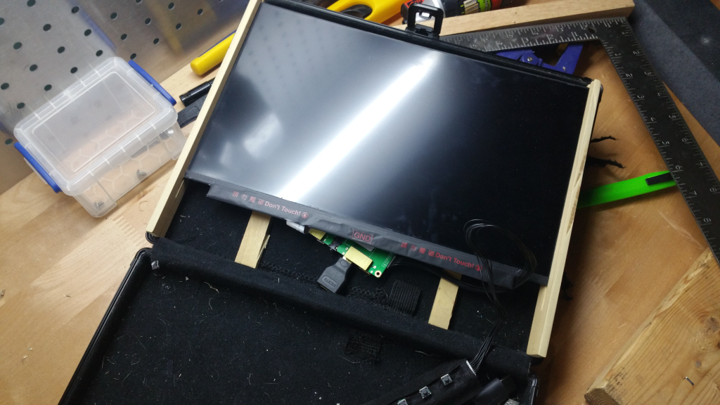
To hold the display in the top of the case I used velcro cable ties. Because the housing has all that felt lining, I was able to just use the cable ties like tape to hold everything in place. I did have to cut out the original netting that was in the top. A few minutes with a pocket knife left the top fairly smooth and totally velcroable. I attached the screen to the top and all my other components to the bottom. This worked well enough that I could cart the thing around and still use it as a kind of laptop. That way I could show it to a few other hobbyists and get some ideas on how to make it more of a laptop.
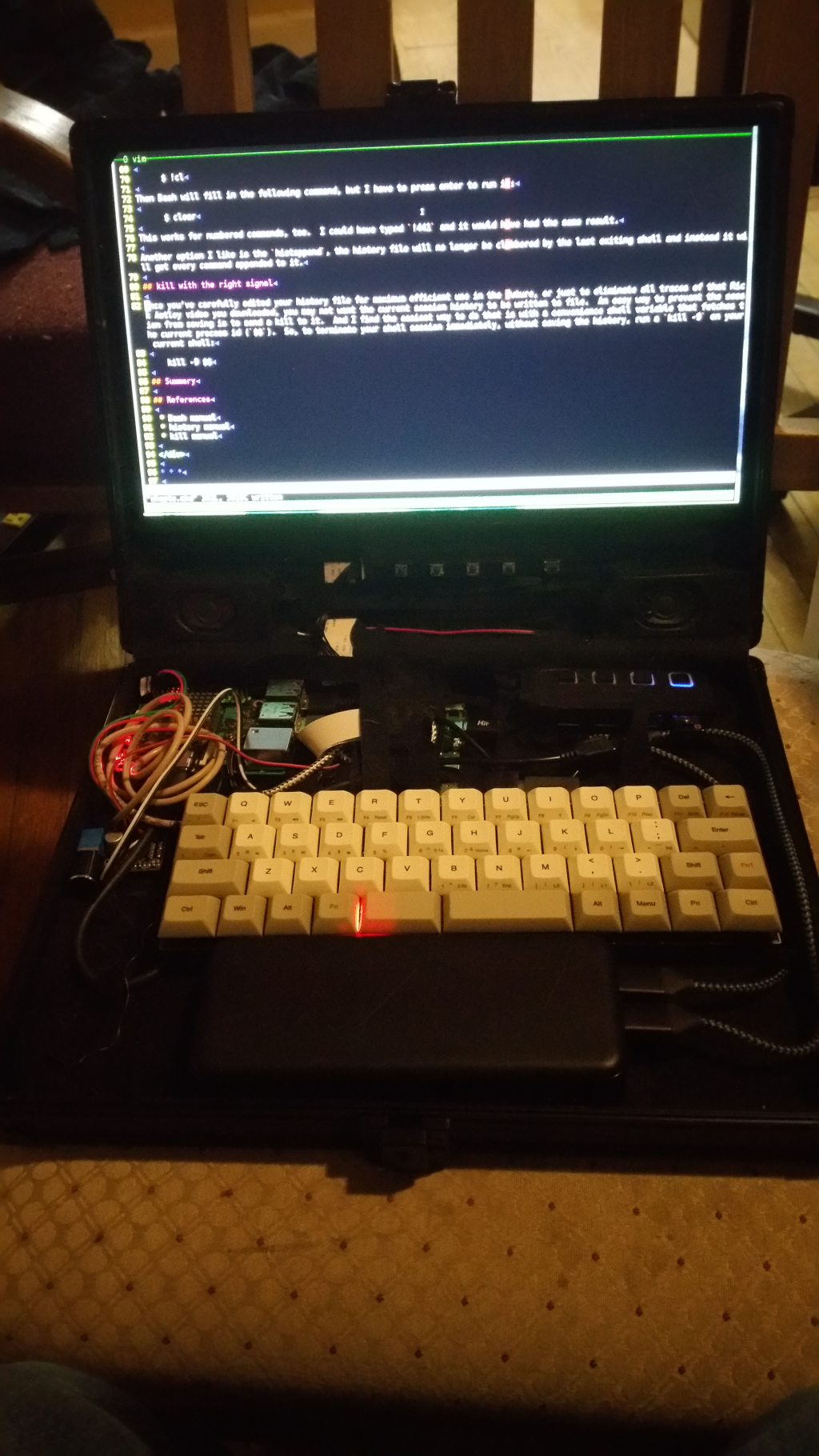
Here's a super blurry, fuzzy, and dark image of what that looked like. Sorry, I thought I had taken more pictures of it, but in going back through my images I couldn't find a better one.
I showed it to a fellow steemian that has a few wood working tools, and his first thought for the screen was to create a frame for the LCD by grooving a couple pieces of wood and sliding the screen into the groove, and then sliding the frame into the housing. (He's working on a pretty cool piece of furniture that I'm trying to get him to post, but we'll see where that goes.)
The Frame
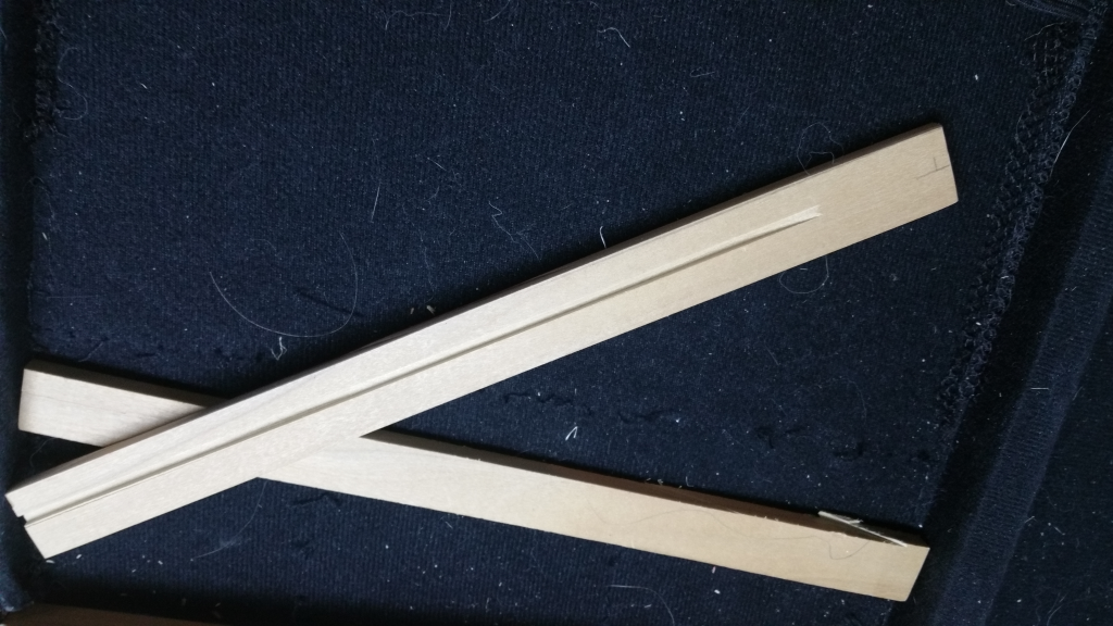
Given the dimensions of the screen and the housing, there was only about an eighth of an inch to work with, so the total width of the wood needed to be less than an eight of an inch. The smallest scrap wood he had lying around was an eight of an inch thick. Some sort of maple, I think. Now, for those who can math, two pieces of eighth inch thick wood is bigger than an eighth of an inch, so we made a groove one sixteenth of an inch in each piece so so the screen would still, hypothetically fit.
Remember that felt lining? After grooving the frame, the lining proved to make the grooves too shallow. But taking the grooves any further would have been structurally too weak. So, it was time to investigate that lining.
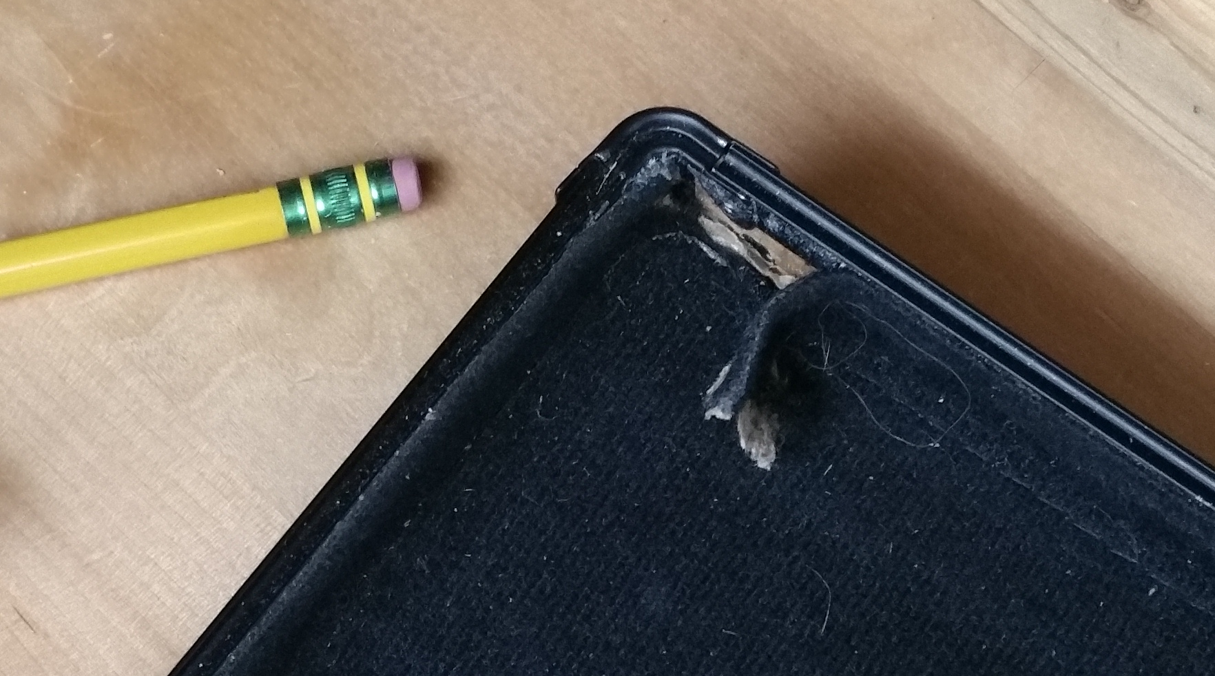
It looked a bit ugly behind the lining. There was some lining and some cardboard, so I stripped the lining out of there with an Exacto knife and cleaned up the cardboard a bit.
It looked like what you might expect.
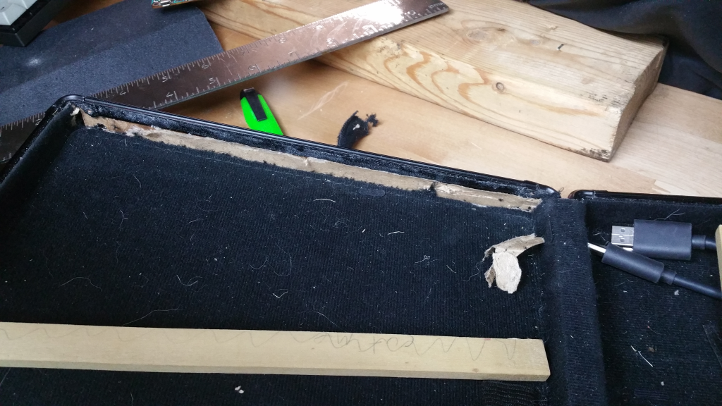
I removed it from both sides and then confirmed that I could get the frame pieces into place. It was a bit of a tight fit, but the friction would mean less work to mount the frame to the housing. Next was actually getting the frame and the LCD into the housing. Sliding everything into place before actually seating the frame in the housing revealed that some more work needed to be done.
Everything looked great, but too much force was needed to fit the frame and the LCD into the housing, I was worried that I might put too much force on the LCD and crack it. So I set about sanding. A lot of sanding. I got the frame to the point where it would slide into place easily and I was able to fit the LCD in. But now there was a gap below the frame. I wanted to put the speakers there, much like in the taped up version, but I also wanted to hide that LCD controller board behind the screen.
Well, thanks to needing a mini HDMI cable, I couldn't mount it perfectly behind the screen, and I actually had to put it at a weird angle so the adapter would fit. I've actually ordered another adapter so I can fix this. The cabling is a little too tight to rely on friction to hold in the next piece I would make.
The Faceplate
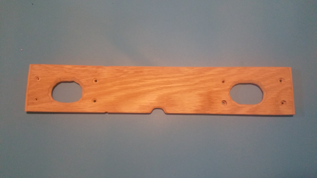
I wanted a face plate for below the screen. If anyone has ever needed to make ovular holes for a speaker to peak out from behind a wooden face plate, don't bother with a drill unless you have a drill press. I butchered the holes and now my speaker slots look like a child's attempt to make eyes on some kind of googly eyed monster. Instead, just use a Dremel. I was able to fix up most of my mistakes with a Dremel after, even though it's still kind of googley-eyed.
The Wrap-up
You can see all the bits in this final image, which is way too dark on the actual laptop, and I didn't notice that I had actually cut the bottom off. If it brightens up enough today, I'll take the whole thing outside and take a nice clear picture of it. The artificial lights in here just aren't cutting it.
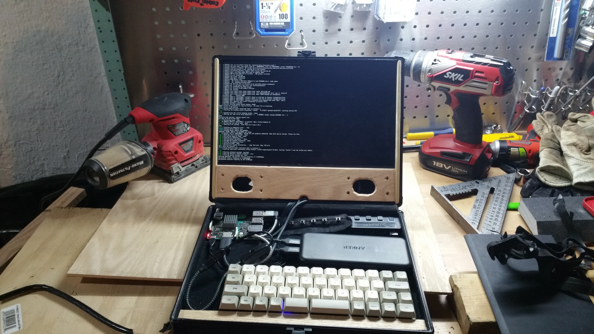
A second picture, taken later in the day (of the day I posted) but still not very bright. However, you can see the speakers, sort of, in the face plate. They're nice and loud, they just look sloppy. But, maybe the next revision will clean that up.
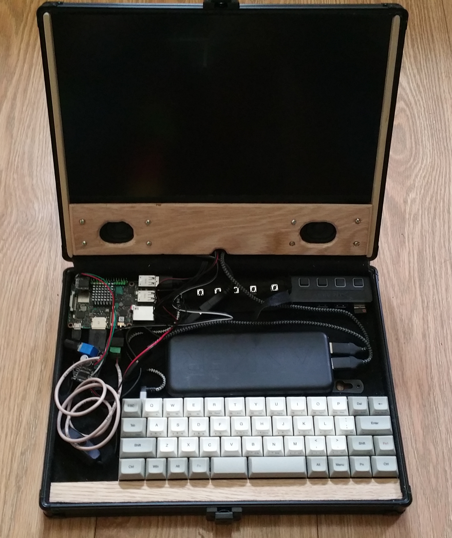
I still need to buy bought some nuts and bolts to mount the speakers in their holes, but I have to fix the pockets for the screw holes, now, and when my new mini HDMI adapter arrives I can make the cables fit behind the face plate much better. I might even have room to mount the SBC under the face plate, which would free up more room in the bottom of the case so it's less awkward to get at the USB hub, for example.
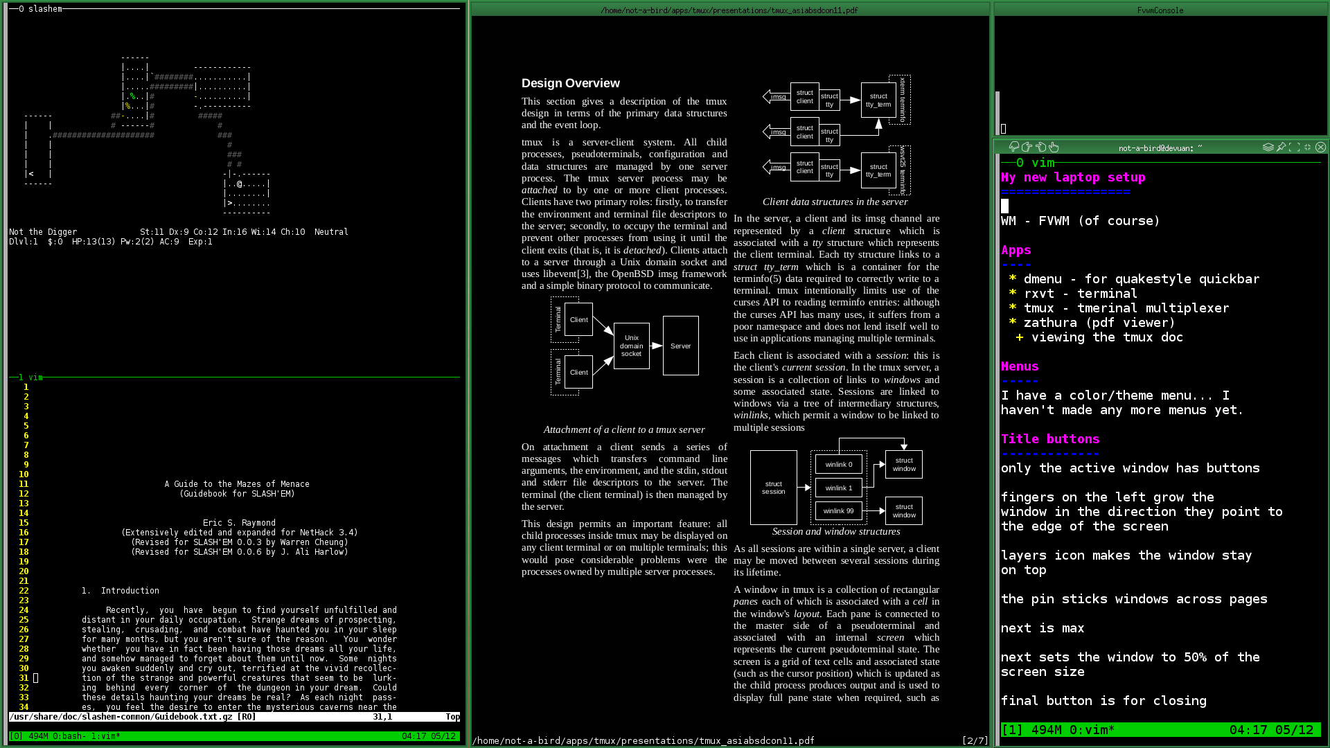
And about those software changes, if I can find the time, I'll post some more about the user interface changes I'm making. For now, here's a glimpse of what that kind of looks like:
Previous posts in this series:
speaking of #GooglyEyes, an actual pair of those might just add a nice touch of character to your little beast...
oh... and no discouragement... because what you're doing there is friggin awesome... but have you ever heard of a motorola lapdock? Turns a Raspberry into a laptop (including battery supply) with just 2 adaptors and you can find them for pretty cheap on ebay every now and then...
Yeah, I bought one. Then found out that none of my HDMI cables had the magic activeness to it, so it didn't work. There it sits on my shelf... I tried a few different tutorials on getting it to work, all to no avail. The damn thing turns itself off and then the pi loses power...
In my setup here, though, I wasn't terribly clear, I'm using a pi clone that needs pretty high amperage for good performance. If I could figure out how to get the lapdock to work, I dont think it would provide enough current... .or maybe it would. Frustration has me done with that thing.
Edit: Maybe I'll put some eyebrows above the speakers...
This is an incredibly cool project, much kudos to you!
Thanks! I expected a more common response would be "Why are you doing this?!" or "Wow, that's going to be way more expensive than just buying a laptop!" For neither reply would I have a very good answer...
The journey of building it is part of the fun ;)
Very cool!!!
You're Beautiful