Fan Filter Unit Explained: How FFUs Power Every Modern Cleanroom
Introduction – The Heartbeat of Cleanroom Air Quality
Every cleanroom depends on one critical component to deliver continuous, particle-free air: the fan filter unit. Whether you operate a semiconductor fab, a pharmaceutical filling line, or a biotech research lab, the fan filter unit FFU sits at the center of your contamination control strategy. This guide breaks down how FFUs work, what types exist, and why cleanroom designers worldwide choose them over traditional ducted systems.
What Is a Fan Filter Unit? Core Components and Working Principle
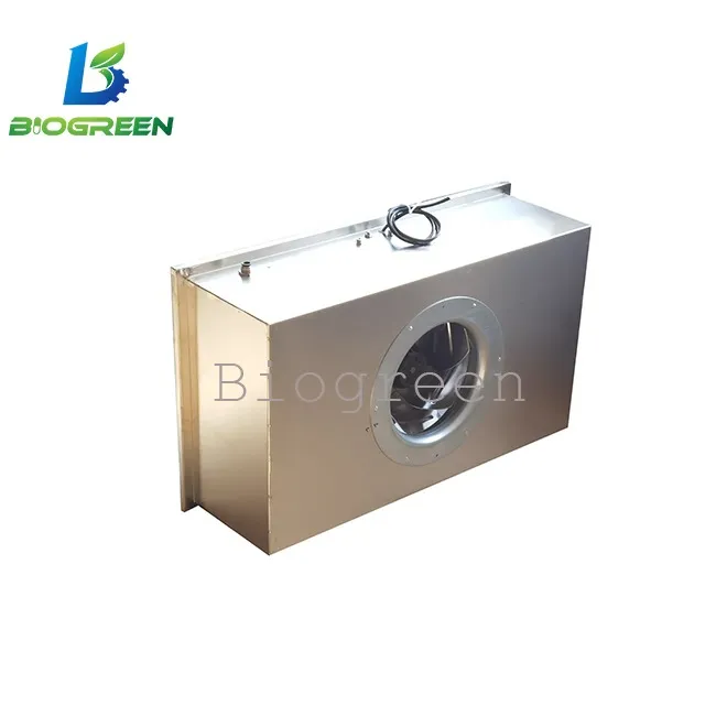
A fan filter unit combines a motorized fan with a high-efficiency particulate filter inside a compact, modular housing. The fan draws ambient or recirculated air into the unit, pushes it through the filter media, and delivers ultra-clean air downward into the cleanroom space.
Core components include:
EC or AC motor-driven fan– generates consistent, adjustable airflow
HEPA or ULPA filter– captures airborne particles down to 0.3 µm or 0.12 µm
Housing/frame– typically aluminum or galvanized steel, sized to fit standard ceiling grids
Pre-filter layer (optional)– extends the main filter’s service life
The working principle is straightforward: the fan creates positive pressure above the filter, forcing air through the media at a uniform velocity. This process removes contaminants before they ever reach the workspace below.
FFU Clean Room
How a Filter Fan Unit Creates Laminar Airflow and Maintains ISO Classifications
Cleanrooms require unidirectional (laminar) airflow to sweep particles away from critical surfaces. Each filter fan unit delivers a vertical column of clean air at a typical face velocity of 0.35–0.55 m/s. When engineers install multiple FFUs across a ceiling grid, these individual columns merge into a uniform downward air curtain.
This laminar flow pattern directly supports ISO 14644-1 classifications. An ISO Class 5 cleanroom, for example, often requires 80–100% ceiling coverage with FFU fan filter units, while an ISO Class 7 space may need only 15–25% coverage. Adjusting FFU quantity and fan speed gives facility managers precise control over particle counts.
Types of FFUs: HEPA-Based vs. ULPA-Based
Feature
HEPA FFU
ULPA FFU
Efficiency
99.97% at 0.3 µm
99.9995% at 0.12 µm
Typical application
ISO 5–7 cleanrooms
ISO 3–5 cleanrooms
Pressure drop
Lower
Higher
Energy use
Moderate
Higher
Cost
Lower upfront
Premium
Most pharmaceutical and electronics assembly environments rely on HEPA-based fan filter units. Semiconductor lithography bays and advanced nanotechnology labs typically specify ULPA-based units when even a single sub-micron particle poses unacceptable risk.
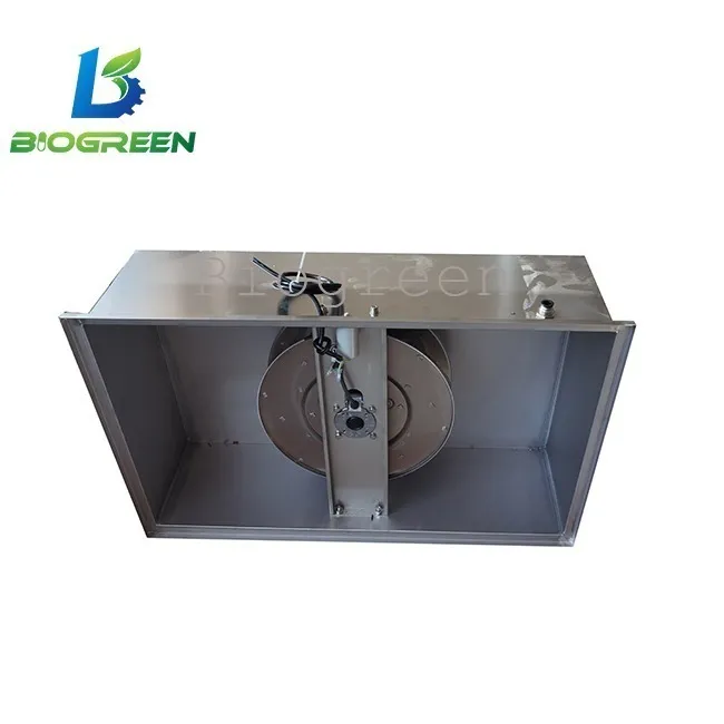
FFU Clean Room
FFU Sizing, Airflow Rates, and Energy Consumption
Standard FFU sizes match common ceiling grid modules: 2 ft × 4 ft (610 × 1220 mm) and 4 ft × 4 ft (1220 × 1220 mm). Airflow rates range from 500 to 1,400 CFM depending on size and motor speed setting.
Energy consumption matters enormously at scale. A single FFU fan filter unit may draw 100–350 watts, but a large fab running hundreds of units accumulates significant electrical costs. EC (electronically commutated) motors reduce energy consumption by 30–50% compared to AC motors, and variable-speed controllers let operators match airflow to real-time cleanliness requirements.
Integration with Cleanroom Ceiling Grid Systems
Modular design makes the fan filter unit exceptionally easy to integrate. Each unit drops into a T-bar ceiling grid, connects to single-phase power, and begins operating immediately. Facilities can add or relocate units as production layouts change—no ductwork modifications required.
This plug-and-play flexibility supports rapid cleanroom expansion, a major advantage for growing operations.
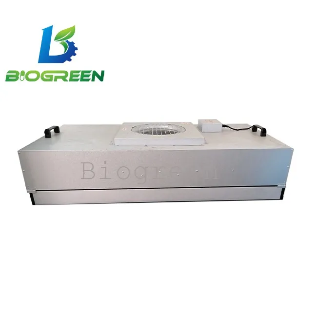
FFU Clean Room
FFU-Driven Cleanrooms vs. Ducted HVAC Cleanrooms
Ducted systems channel air through central air handling units and extensive sheet-metal ductwork. FFU-driven cleanrooms eliminate most of that ductwork, distributing filtration across many independent units. Key advantages of the FFU approach include:
Lower construction cost– less ductwork, simpler plenum
Scalability– add units without redesigning the HVAC system
Redundancy– one failed unit does not shut down the entire cleanroom
Faster installation– modular setup reduces project timelines
Ducted systems still suit large centralized facilities that require tight temperature and humidity control at the air handler level, but most modern cleanroom projects favor FFU-based designs for their flexibility.
Key Performance Metrics to Evaluate Before Purchasing
Before selecting a fan filter unit, evaluate these specifications:
Filter efficiency rating– HEPA (H14) or ULPA (U15/U16)
Airflow uniformity– face velocity deviation below ±20%
Noise level– target ≤55 dBA at operating speed
Power consumption– watts per CFM delivered
Filter replacement accessibility– top-change vs. bottom-change design
Motor type– EC motors for long-term energy savings
Requesting third-party test reports for these metrics ensures you compare units on verified data, not marketing claims alone.
Conclusion – Why the Fan Filter Unit Remains the Industry-Standard Choice
The fan filter unit earns its place in virtually every modern cleanroom because it combines high filtration efficiency, modular scalability, and straightforward maintenance in a single compact package. Whether you need a small ISO 7 assembly area or a massive ISO 4 semiconductor fab, FFU fan filter units give you the flexibility to design, build, and expand with confidence. Selecting the right type, size, and motor technology upfront translates directly into cleaner air, lower operating costs, and a contamination control system that grows with your facility.