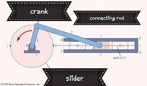
THE CRANK SLIDER MECHANISM
Good day steemians!
this post is just a simple explanation of how the crank slider mechanism works, this mechanism is a simple machanism that was used as early as the 15th century by engineers across Europe and Asia. It was first used in china during the Han Dynasty (202 BC-220 AD) for silk-reeling and hemp-spinning, for the agricultural winnowing fan and in the water-powered flour-sifter.
hence the most common and essential use of a crank and slider mechanism is an Internal Combustion Engine. It is the machanism behind the rotation of the internal combustion engine , this mechanism can also be found in some windows which is operated using links and pin joint.
working principal of a slider crank mechanism
the mechanism is simply the combination of the crank mechanism and the slider mechanism but the combination of both makes a good machine for producing useful work;
▪the crank mechanism : consider a shaft with 3 degree of freedom i.e it is fixed or rather align with two bearing placed at the extreme and it is free to rotate about a given axis and a rod is fixed at one end at right angle to the shaft, when ever the rod is displaced with respect to a circular motion the shaft which is aligned will also rotate, making it easy to rotate the shaft. The force applied to the rod with brings about a turning moment about the shaft, hence the longer the rod the higher the turning moment.
The rod which is fixed at the extreme of the shaft is called the crank while the shaft which is aligned with two bearings is called the crank shaft.
▪the slider mechanism: the slider is simply a bar which movement is restricted to a given straight line. It has 1 degree of freedom and is mostly characterise with a to and fro motion within a given span, it main function is just to support link to a certain machine meanwhile force can be applied to it and will cause a motion on the link fixed to it or may even cause motion to the whole machine links. the process above can also be reverse in that force can be applied to the links which may cause motion on the slider.
the combination of both forms the slider crank mechanism, in this mechanism a link connects the slider and the crank together which is called the connecting rod, under normal condition the length of the connecting rod is always longer than that of the crank to enable the rotation of the crank rod.
Basically a crank slider mechanism converts reciprocating motion to rotational motion by virtue of force and moment. the basic principle of this mechanism is that as the slider moves back and forth it pushes the connecting rod link which then transfer the force to the crank link and the crankshaft then exhibit a rotational motion due to the moment applied by the crank.
If more than one crank slider machanism are placed on one single shaft, it forms the basis of the internal combustion engine with a defined timing system, and the force applied is an explosion of gas in a confined space wich pushes the slider to cause motion in both the connecting rod and crank links.
ANTICIPATING A POST ON I.C.E

