Neuralink - An integrated brain-machine interface platform with thousands of channels
An integrated brain-machine interface platform with thousands of channels
Elon Musk & Neuralink
Abstract
Brain-machine interfaces (BMIs) hold promise for the restoration of sensory and motor function and the treatment of neurological disorders, but clinical BMIs have not yet been widely adopted, in part because modest channel counts have limited their potential. In this white paper, we describe Neu-ralink’s first steps toward a scalable high-bandwidth BMI system. We have built arrays of small and flexible electrode “threads”, with as many as 3,072 electrodes per array distributed across 96 threads. We have also built a neurosurgical robot capable of inserting six threads (192 electrodes) per minute. Each thread can be individually inserted into the brain with micron precision for avoidance of sur-face vasculature and targeting specific brain regions. The electrode array is packaged into a small implantable device that contains custom chips for low-power on-board amplification and digitiza-tion: the package for 3,072 channels occupies less than( 23 × 18. 5 × 2 )mm^3. A single USB-C cable provides full-bandwidth data streaming from the device, recording from all channels simultaneously. This system has achieved a spiking yield of up to 85.5% in chronically implanted electrodes. Neu-ralink’s approach to BMI has unprecedented packaging density and scalability in a clinically relevant
package.
1 Introduction
Brain-machine interfaces (BMIs) have the potential to help people with a wide range of clinical disorders. For example,
researchers have demonstrated human neuroprosthetic control of computer cursors [1, 2, 3], robotic limbs [4, 5], and
speech synthesizers [6] using no more than 256 electrodes. While these successes suggest that high fidelity information
transfer between brains and machines is possible, development of BMI has been critically limited by the inability to
record from large numbers of neurons. Noninvasive approaches can record the average of millions of neurons through
the skull, but this signal is distorted and nonspecific [7, 8]. Invasive electrodes placed on the surface of the cortex can
record useful signals, but they are limited in that they average the activity of thousands of neurons and cannot record
signals deep in the brain [9]. Most BMI’s have used invasive techniques because the most precise readout of neural repre-
sentations requires recording single action potentials from neurons in distributed, functionally-linked ensembles [10].
Microelectrodes are the gold-standard technology for recording action potentials, but there has not been a clinically-
translatable microelectrode technology for large-scale recordings [11]. This would require a system with material prop-
erties that provide high biocompatibility, safety, and longevity. Moreover, this device would also need a practical surgi-
cal approach and high-density, low-power electronics to ultimately facilitate fully-implanted wireless operation.
Most devices for long-term neural recording are arrays of electrodes made from rigid metals or semiconductors [12, 13,
14, 15, 16, 17, 18]. While rigid metal arrays facilitate penetrating the brain, the size, Young’s modulus and bending stiff-
ness mismatches between stiff probes and brain tissue can drive immune responses that limit the function and longevity
of these devices [19, 11]. Furthermore, the fixed geometry of these arrays constrains the populations of neurons that
can be accessed, especially due to the presence of vasculature.
An alternative approach is to use thin, flexible multi-electrode polymer probes [20, 21]. The smaller size and increased
flexibility of these probes should offer greater biocompatibility. However, a drawback of this approach is that thin poly-
mer probes are not stiff enough to directly insert into the brain; their insertion must be facilitated by stiffeners [22, 21],
injection [23, 24] or other approaches [25], all of which are quite slow [26, 27]. To satisfy the functional requirements for
a high-bandwidth BMI, while taking advantage of the properties of thin-film devices, we developed a robotic approach,
It is made available under a CC-BY-ND 4.0 International license.
was not peer-reviewed) is the author/funder, who has granted bioRxiv a license to display the preprint in perpetuity.
July 16, 2019
where large numbers of fine and flexible polymer probes are efficiently and independently inserted across multiple brain
regions [28].
Here, we report Neuralink’s progress towards a flexible, scalable BMI that increases channel count by an order of mag-
nitude over prior work. Our system has three main components: ultra-fine polymer probes (section 2 of this report), a
neurosurgical robot (section 3), and custom high-density electronics (section 4). We demonstrate the rapid implanta-
tion of 96 polymer threads, each thread with 32 electrodes, in a( 4 × 7 )mm^2 area of brain for a total of 3,072 electrodes.
We developed miniaturized custom electronics that allow us to stream full broadband electrophysiology data simul-
taneously from all these electrodes (section 5). We packaged this system for long-term implantation and developed
custom online spike detection software that can detect action potentials with low latency. Together, this system serves
as a state-of-the-art research platform and a first prototype towards a fully implantable human BMI.
2 Threads
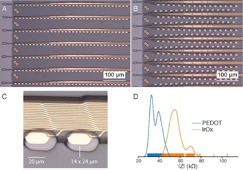
Figure 1: Our novel polymer probes. A. “Linear Edge” probes, with 32 electrode contacts spaced by 50μm. B. “Tree”
probes with 32 electrode contacts spaced by 75μm. C. Increased magnification of individual electrodes for the thread
design in panel A, emphasizing their small geometric surface area. D. Distribution of electrode impedances (measured
at 1kHz) for two surface treatments: PEDOT (n=257) and IrOx (n=588).
We have developed a custom process to fabricate minimally displacive neural probes that employ a variety of biocom-
patible thin film materials. The main substrate and dielectric used in these probes is polyimide, which encapsulates
a gold thin film trace. Each thin film array is composed of a “thread” area that features electrode contacts and traces
and a “sensor” area where the thin film interfaces with custom chips that enable signal amplification and acquisition.
A wafer-level microfabrication process enables high-throughput manufacturing of these devices. Ten thin film devices
are patterned on a wafer, each with 3,072 electrode contacts.
Each array has 48 or 96 threads, each of those containing 32 independent electrodes. Integrated chips are bonded to the
contacts on the sensor area of the thin film using a flip-chip bonding process. One goal of this approach is to maintain
It is made available under a CC-BY-ND 4.0 International license.
was not peer-reviewed) is the author/funder, who has granted bioRxiv a license to display the preprint in perpetuity.
July 16, 2019
a small thread cross-sectional area to minimize tissue displacement in the brain. To achieve this, while keeping channel
count high, stepper lithography and other microfabrication techniques are used to form the metal film at sub-micron
resolution.
We have designed and manufactured over 20 different thread and electrode types into our arrays; two example designs
are shown in panels A and B of fig. 1. We have fabricated threads ranging from 5 to 50μm in width that incorporate
recording sites of several geometries (fig. 1). Thread thickness is nominally 4 to 6μm, which includes up to three layers
of insulation and two layers of conductor. Typical thread length is approximately 20mm. To manage these long, thin
threads prior to insertion, parylene-c is deposited onto the threads to form a film on which the threads remain attached
until the surgical robot pulls them off. Each thread ends in a( 16 × 50 )μm^2 loop to accommodate needle threading.
Since the individual gold electrode sites have small geometric surface areas (fig. 1C), we use surface modifications to
lower the impedance for electrophysiology and increase the effective charge-carrying capacity of the interface (fig. 1D).
Two such treatments that we have used are the electrically conductive polymer poly-ethylenedioxythiophene doped
with polystyrene sulfonate (PEDOT:PSS) [29, 30] and iridium oxide (IrOx) [31, 32]. In bench-top testing we have
achieved impedances of 36. 97 ± 4 .68kΩ (n=257electrodes) and 56. 46 ± 7 .10kΩ (n=588) for PEDOT:PSS and
IrOx, respectively. The lower impedance of PEDOT:PSS is promising, however the long-term stability and biocompati-
bility of PEDOT:PSS is less well established than for IrOx. These techniques and processes can be improved and further
extended to other types of conductive electrode materials and coatings.
3 Robot
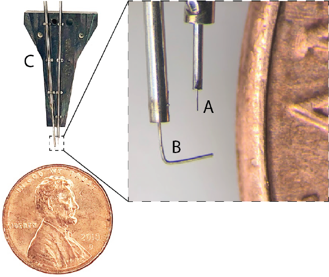
Figure 2: Needle pincher cartridge (NPC) compared with a penny for scale. A. Needle. B. Pincher. C. Cartridge.
Thin-film polymers have previously been used for electrode probes [21], but their low bending stiffness complicates
insertions. Neuralink has developed a robotic insertion approach for inserting flexible probes [28], allowing rapid and
reliable insertion of large numbers of polymer probes targeted to avoid vasculature and record from dispersed brain
regions. The robot’s insertion head is mounted on 10μm globally accurate, 400mm×400mm×150mm travel three-
axis stage, and holds a small, quick-swappable, “needle-pincher” assembly (fig. 2, fig. 3A).
The needle is milled from 40μm diameter tungsten-rhenium wire-stock electrochemically etched to 24μm diameter
along the inserted length (fig. 2A). The tip of the needle is designed both to hook onto insertion loops—for transporting
and inserting individual threads—and to penetrate the meninges and brain tissue. The needle is driven by a linear motor
allowing variable insertion speeds and rapid retraction acceleration (up to 30,000mms−^2 ) to encourage separation of
It is made available under a CC-BY-ND 4.0 International license.
was not peer-reviewed) is the author/funder, who has granted bioRxiv a license to display the preprint in perpetuity.
July 16, 2019
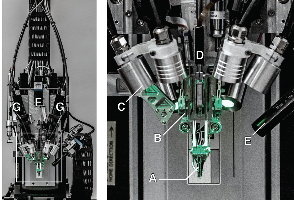
Figure 3: The robotic electrode inserter; enlarged view of the inserter-head shown in the inset. A. Loaded needle
pinchercartridge. B. Low-forcecontactbrainpositionsensor. C. Lightmoduleswithmultipleindependentwavelengths.
D. Needle motor. E. One of four cameras focused on the needle during insertion. F. Camera with wide angle view of
surgical field. G. Stereoscopic cameras.
the probe from the needle. The pincher is a 50μm tungsten wire bent at the tip and driven both axially and rotationally
(fig. 2B). It serves as support for probes during transport and as a guide to ensure that threads are inserted along the
needle path. Figure 4 shows a sequence of photographs of the insertion process into an agarose brain proxy.
The inserter head also holds an imaging stack (fig. 3E–G) used for guiding the needle into the thread loop, insertion tar-
geting, live insertion viewing, and insertion verification. In addition, the inserter head contains six independent light
modules, each capable of independently illuminating with 405nm, 525nm and 650nm or white light (fig. 3C). The
405nm illumination excites fluorescence from polyimide and allows the optical stack and computer vision to reliably
localize the( 16 × 50 )μm^2 thread loop and execute sub-micron visual servoing to guide, illuminated by 650nm the nee-
dle through it. Stereoscopic cameras, software based monocular extended depth of field calculations, and illumination
with 525nm light allow for precise estimation of the location of the cortical surface.
The robot registers insertion sites to a common coordinate frame with landmarks on the skull, which, when combined
with depth tracking, enables precise targeting of anatomically defined brain structures. An integrated custom software
suite allows pre-selection of all insertion sites, enabling planning of insertion paths optimized to minimize tangling and
strain on the threads. The planning feature highlights the ability to avoid vasculature during insertions, one of the key
advantages of inserting electrodes individually. This is particularly important, since damage to the blood-brain barrier
is thought to play a key role in the brain’s inflammatory response to foreign objects [33].
The robot features an auto-insertion mode, which can insert up to 6 threads (192 electrodes) per minute. While the
entire insertion procedure can be automated, the surgeon retains full control, and if desired, can make manual micro-
adjustments to the thread position before each insertion into the cortex. The neurosurgical robot is compatible with
sterile shrouding, and has features to facilitate successful and rapid insertions such as automatic sterile ultrasonic clean-
ing of the needle. The needle pincher cartridge (NPC; fig. 2C) is the portion of the inserter head that makes direct
contact with brain tissue and is a consumable that can be replaced mid-surgery in under a minute.
It is made available under a CC-BY-ND 4.0 International license.
was not peer-reviewed) is the author/funder, who has granted bioRxiv a license to display the preprint in perpetuity.
July 16, 2019
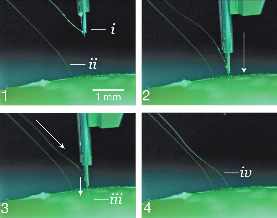
Figure 4: 1. The inserter approaches the brain proxy with a thread.i.needle and cannula.ii.previously inserted thread.
2. Inserter touches down on the brain proxy surface. 3. Needle penetrates tissue proxy, advancing the thread to the
desired depth.iii.inserting thread. 4. Inserter pulls away, leaving the thread behind in the tissue proxy.iv.inserted
thread.
With this system, we have demonstrated an average of 87. 1 ± 12 .6% (mean±s.d.) insertion success rate over 19 surg-
eries. In this study, precise manual adjustments were made to avoid microvasculature on the cortical surface, slowing
total insertion time from the fastest possible. Even with these adjustments, the total insertion time for this study av-
eraged∼45min, for an approximate insertion rate of 29.6 electrodes per minute (fig. 6). Insertions were made in a
( 4 × 7 )mm^2 bilateral craniotomy with>300μm spacing between threads to maximize cortical coverage. This demon-
strates that robotic insertion of thin polymer electrodes is an efficient and scalable approach for recording from large
numbers of neurons in anatomically defined brain regions.
4 Electronics
Chronic recording from thousands of electrode sites presents significant electronics and packaging challenges. The den-
sity of recording channels necessitates placing the signal amplification and digitization stack within the array assembly,
otherwise the cable and connector requirements would be prohibitive. This recording stack must amplify small neural
signals (<10μVRMS) while rejecting out-of-band noise, sample and digitize the amplified signals, and stream out the
results for real-time processing—all using minimal power and size.
The electronics are built around our custom Neuralink application specific integrated circuit (ASIC), which consists of
256 individually programmable amplifiers (“analog pixels”), on-chip analog-to-digital converters (ADCs), and periph-
eral control circuitry for serializing the digitized outputs. The analog pixel is highly configurable: the gains and filter
It is made available under a CC-BY-ND 4.0 International license.
was not peer-reviewed) is the author/funder, who has granted bioRxiv a license to display the preprint in perpetuity.
July 16, 2019
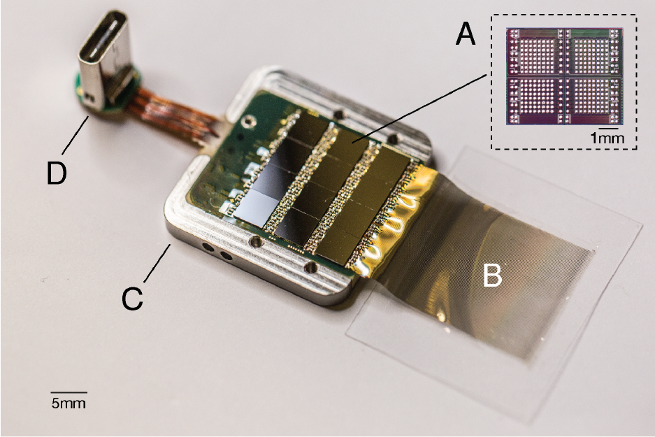
Figure 5: A packaged sensor device. A. individual neural processing ASIC capable of processing 256 channels of data.
Thisparticularpackageddevicecontains12ofthesechipsforatotalof3,072channels. B. Polymerthreadsonparylene-c
substrate. C. Titanium enclosure (lid removed). D. Digital USB-C connector for power and data.
properties can be calibrated to account for variability in signal-quality due to process variations and the electrophysio-
logical environment. The on-chip ADC samples at 19.3kHz with 10bit resolution. Each analog pixel consumes 5.2μW
and the whole ASIC consumes∼6mW, including the clock drivers. Performance of the Neuralink ASIC is summarized
in table 1 and a photograph of the fabricated device is shown in fig. 5A.
The Neuralink ASIC forms the core of a modular recording platform that allows for easy replacement of constitutive
parts for research and development purposes (fig. 5). In the systems discussed here, a number of ASICs are integrated
into a standard printed circuit board (PCB) using flip-chip integration. Each system consists of a field-programmable
gate array (FPGA); real-time temperature, accelerometer, and magnetometer sensors; and a single USB-C connector
for full-bandwidth data transfer. The systems are packaged in titanium cases which are coated with parylene-c, which
serves as a moisture barrier to prevent fluid ingress and prolong functional lifetime.
We describe two such configurations that we have built, a 1,536 channel recording system (“System A”) and a 3, 072
channel recording system (“System B”), summarized in table 2. While System A employs the current-generation Neu-
ralink ASIC, System B uses an earlier revision with comparable functionality but poorer performance specifications.
System B was designed to maximize channel density and is used for applications that demand extremely high channel
count. In contrast, System A was designed to facilitate faster and more reliable manufacturing; it can be built five times
faster than System B with better yields.
An ethernet-connected base station converts the data streams from these systems into multicast 10G ethernet UDP
packets allowing downstream users to process the data in a variety of ways, e.g. visualizing the data in real-time or
writing it to disk. Each base station can connect to up to three implants simultaneously. These devices are further
supported by a software ecosystem that allows for plug and play usability with zero configuration: neural data begins
streaming automatically when a cable is connected.
It is made available under a CC-BY-ND 4.0 International license.
was not peer-reviewed) is the author/funder, who has granted bioRxiv a license to display the preprint in perpetuity.
July 16, 2019

Table 1: Neuralink ASIC
Number of Channels 256
Gain 42 .9–59.4dB
Bandwidth 3Hz–27kHz
Input-referred noise (3Hz - 10KHz) 5 .9μVRMS
Maximum Differential Input Range 7 .2mVPP
ADC resolution 10bit
Analog Pixel Power 5 .2μW
Table 2: Two recording system configurations
System A System B
Number of Channels 1 , 536 3 , 072
Sampling Rate 19 .3kHz 18 .6kHz
Total System Power Consumption 550mW 750mW
Total System Size ( 24. 5 × 20 × 1. 65 )mm^3 ( 23 × 18. 5 × 2 )mm^3
5 Electrophysiology
We have implanted both systems A and B in male Long-Evans rats, as described in section 3. All animal procedures were
performed in accordance with the National Research Council’sGuide for the Care and Use of Laboratory Animalsand
were approved by the Neuralink Institutional Animal Care and Use Committee. Electrophysiological recordings were
made as the animals freely explored an arena equipped with a commutated cable that permitted unrestricted movement.
System A can record 1,344 out of 1,536 channels simultaneously, the exact channel configuration can be arbitrarily
specified at the time of recording; system B can record from all 3,072 channels simultaneously. Digitized broadband
signals were processed in real-time to identify action potentials (spikes) using an online detection algorithm.
Spike detection requirements for real-time BMI are different from most conventional neurophysiology. While most
electrophysiologists spike-sort data offline and spend significant effort to reject false-positive spike events, BMI events
must be detected in real time and spike detection parameters must maximize decoding efficacy. Using our custom
online spike-detection software, we found that a permissive filter that allows an estimated false positive rate of∼ 0 .2Hz
performs better than setting stringent thresholds that may reject real spikes (data not shown).
Given these considerations, we set a threshold of> 0 .35Hz to quantify the number of electrodes that recorded spiking
units. Since we typically do not spike sort our data, we do not report multiple units per channel. BMI decoders com-
Figure 6: Thread implantation and packaging. A. An example peri-operative image showing the cortical surface with
implanted threads and minimal bleeding. B. Packaged sensor device (“System B”) chronically implanted in a rat.
It is made available under a CC-BY-ND 4.0 International license.
was not peer-reviewed) is the author/funder, who has granted bioRxiv a license to display the preprint in perpetuity.
July 16, 2019
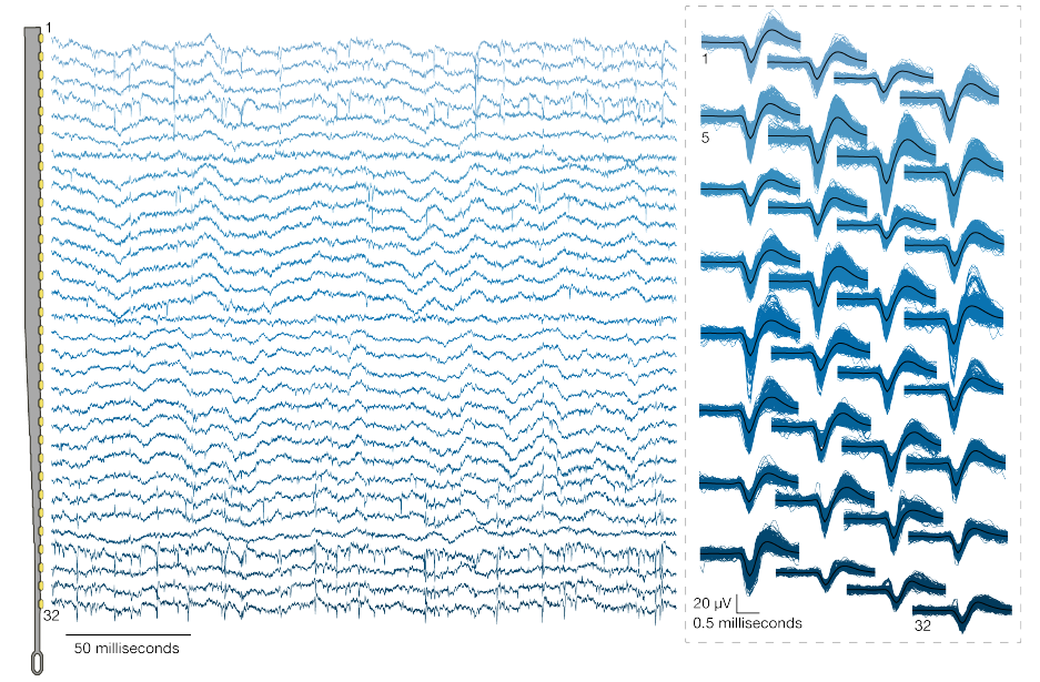
Figure 7: Left: Broadband neural signals (unfiltered) simultaneously acquired from a single thread (32 channels) im-
planted in rat cerebral cortex. Each channel (row) corresponds to an electrode site on the thread (schematic at left;
sites spaced by 50μm). Spikes and local field potentials are readily apparent. Right: Putative waveforms (unsorted);
numbers indicate channel location on thread. Mean waveform is shown in black.
monly operate without spike sorting with minimal loss of performance [35, 36]. Moreover, recent results show that
spike sorting is not necessary to accurately estimate neural population dynamics [37].
Data from a recent experiment using System A are shown in fig. 7 and fig. 8. In this experiment, 40 of 44 attempted
insertions were successful (90%) for a total of 1280 implanted electrodes, of which 1,020 were recorded simultaneously.
The broadband signals recorded from a representative thread show both local field and spiking activity fig. 7. A sample
output of the spike detection pipeline is shown in raster form in fig. 8. In this example, two overlapping recording
configurations were used to record from all 1,280 implanted channels. On this array, our spiking yield was 53.4% of
channels, with many spikes appearing on multiple neighboring channels, as has been observed in other high-density
probes [16, 17, 21]. On other System A arrays we observed 59. 10 ± 5 .74% (mean±s.e.m.) across 19 surgeries with a
maximum spiking yield of 85.5%.
6 Discussion
We have described a BMI with high-channel count and single-spike resolution. It is based on flexible polymer probes,
a robotic insertion system, and custom low-power electronics. This system serves two main purposes: it is a research
platform for use in rodents and serves as a prototype for future human clinical implants. The ability to quickly iterate de-
signs and testing in rodents allows for the rapid refinement of devices, manufacturing processes, and software. Because
it is a research platform, the system uses a wired connection to maximize the bandwidth for raw data streaming. This is
important for performance assessments and crucial for the development of signal processing and decoding algorithms.
In contrast, the clinical devices that will derive from this platform will be fully implantable—which requires hermetic
packaging—and have on-board signal compression, reduced power consumption, wireless power transmission, and
data telemetry through the skin without percutaneous leads.
It is made available under a CC-BY-ND 4.0 International license.
was not peer-reviewed) is the author/funder, who has granted bioRxiv a license to display the preprint in perpetuity.
July 16, 2019
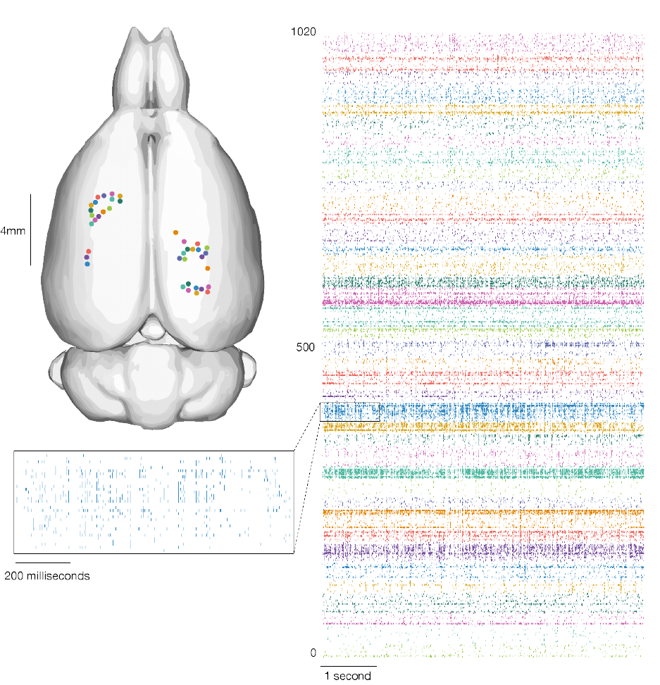
Figure 8: Our devices allow the recording of widespread neural activity distributed across multiple brain regions and
cortical layers. Left: thread insertion sites (colored circles) are indicated on rendered rodent brain. [34] Right: raster of
1 ,020 simultaneously recorded channels, sorted per thread (color corresponds to insertion site). Inset: enlarged raster
of spikes from a single thread. This thread corresponds to the one shown in fig. 7.
It is made available under a CC-BY-ND 4.0 International license.
was not peer-reviewed) is the author/funder, who has granted bioRxiv a license to display the preprint in perpetuity.
July 16, 2019
Modulatingneural activitywill beanimportantpart ofnext-generationclinicalbrain-machineinterfaces[38], forexam-
ple to provide a sense of touch or proprioception to neuroprosthetic movement control [39, 40]. Therefore, we designed
the Neuralink ASIC to be capable of electrical stimulation on every channel, although we have not demonstrated these
capabilities here.
This BMI system has several advantages over previous approaches. The size and composition of the thin-film probes
are a better match for the material properties of brain tissue than commonly used silicon probes, and therefore may
exhibit enhanced biocompatibility [28, 21]. Also, the ability to choose where our probes are inserted, including into
sub-cortical structures, allows us to create custom array geometries for targeting specific brain regions while avoiding
vasculature. This feature is significant for creating a high-performance BMI, as the distribution of electrodes can be
customized depending on the task requirements. Lastly, the miniturization and design of the Neuralink ASIC affords
great flexibility in system design and supports very high channel counts within practical size and power constraints.
In principle, our approach to brain-machine interfaces is highly extensible and scalable. Here we report simultaneous
broadband recording from over 3,000 inserted electrodes in a freely moving rat. In a larger brain, multiple devices with
this architecture could be readily implanted, and we could therefore interface with many more neurons without exten-
sive re-engineering. Further development of surgical robotics could allow us to accomplish this without dramatically
increasing surgery time.
While significant technological challenges must be addressed before a high-bandwidth device is suitable for clinical
application, with such a device, it is plausible to imagine that a patient with spinal cord injury could dexterously control
a digital mouse and keyboard. When combined with rapidly improving spinal stimulation techniques [41], in the future
this approach could conceivably restore motor function. High-bandwidth neural interfaces should enable a variety of
novel therapeutic possibilities.
7 Acknowledgments
We would like to acknowledge the contributions of Lawrence Livermore National Laboratory (LLNL), Berkeley Mar-
vell Nanofabrication Laboratory, Berkeley Wireless Research Center (BWRC), Stanford Nanofabrication Facility, and
former and current Neuralink employees to the work described here.
8 Supplementary Videos
Video 1: A series of six insertions by the neurosurgical robot into an agarose brain proxy. Thread-capture by the
needle occurs off-frame. The changes background color are caused by illumination with different frequencies of light
at different stages of the threading and insertion process. One thread was inserted before the start of the video.
Video 2: A 3D rendered view of thread arrangement (same data presented in fig. 8). Thread insertion is visualized in
the same order as in the actual surgery, but time has been compressed for presentation. Thread size and insertion depth
are representative. The stereotaxic coordinates of each insertion are represented on the dataset provided by Calabrese
and coworkers [34].
References
[1] Leigh R. Hochberg et al. “Neuronal ensemble control of prosthetic devices by a human with tetraplegia”. In:
Nature442 (2006), p. 164. issn: 1476-4687.
[2] Wei Wang et al. “An Electrocorticographic Brain Interface in an Individual with Tetraplegia”. In:PLoS ONE 8
(2013), e55344.
[3] TysonAflaloetal.“Decodingmotorimageryfromtheposteriorparietalcortexofatetraplegichuman”.In:Science
348 (2015), pp. 906–910. issn: 0036-8075.
[4] Leigh R. Hochberg et al. “Reach and grasp by people with tetraplegia using a neurally controlled robotic arm”. In:
Nature485 (2012), p. 372. issn: 1476-4687.
[5] Jennifer L Collinger et al. “High-performance neuroprosthetic control by an individual with tetraplegia”. In:The
Lancet381 (2013), pp. 557–564. issn: 0140-6736.
[6] Gopala K. Anumanchipalli, Josh Chartier, and Edward F. Chang. “Speech synthesis from neural decoding of
spoken sentences”. In:Nature568 (2019), pp. 493–498. issn: 0028-0836.
[7] György Buzsáki, Costas A. Anastassiou, and Christof Koch. “The origin of extracellular fields and currents —
EEG, ECoG, LFP and spikes”. In:Nature Reviews Neuroscience13 (2012), p. 407. issn: 1471-0048.
It is made available under a CC-BY-ND 4.0 International license.
was not peer-reviewed) is the author/funder, who has granted bioRxiv a license to display the preprint in perpetuity.
July 16, 2019
[8] Bijan Pesaran et al. “Investigating large-scale brain dynamics using field potential recordings: analysis and inter-
pretation”. In:Nature Neuroscience21 (2018), pp. 903–919. issn: 1097-6256.
[9] Taro Kaiju et al. “High Spatiotemporal Resolution ECoG Recording of Somatosensory Evoked Potentials with
Flexible Micro-Electrode Arrays”. In:Frontiers in Neural Circuits11 (2017), p. 20.
[10] Rafael Yuste. “From the neuron doctrine to neural networks”. In:Nature Reviews Neuroscience16 (2015), pp. 487–
- issn: 1471-003x.
[11] Guosong Hong and Charles M Lieber. “Novel electrode technologies for neural recordings”. In:Nature Reviews
Neuroscience(2019), pp. 1–16. issn: 1471-003X.
[12] Edwin M. Maynard, Craig T. Nordhausen, and Richard A. Normann. “The Utah Intracortical Electrode Array: A
recording structure for potential brain-computer interfaces”. In:Electroencephalography and Clinical Neurophys-
iology102.3 (1997), pp. 228–239. issn: 0013-4694.
[13] Miguel A. L. Nicolelis et al. “Chronic, multisite, multielectrode recordings in macaque monkeys”. In:Proceedings
of the National Academy of Sciences100.19 (2003), pp. 11041–11046. issn: 0027-8424. eprint:https://www.
pnas.org/content/100/19/11041.full.pdf.
[14] K. D. Wise et al. “Microelectrodes, Microelectronics, and Implantable Neural Microsystems”. In:Proceedings of
the IEEE96.7 (2008), pp. 1184–1202. issn: 0018-9219.
[15] NicholasM. Dotson et al. “A Large-Scale Semi-Chronic MicrodriveRecording System forNon-Human Primates”.
In:Neuron96 (2017), 769–782.e2. issn: 0896-6273.
[16] James J. Jun et al. “Fully integrated silicon probes for high-density recording of neural activity”. In:Nature 551
(2017), p. 232. issn: 1476-4687.
[17] Gian Nicola Angotzi et al. “SiNAPS: an implantable Active Pixel Sensor CMOS-probe for Simultaneous large-
scale Neural recordings”. In:Biosensors and Bioelectronics126 (2018), pp. 355–364.issn: 0956-5663.
[18] Felix Deku et al. “Amorphous silicon carbide ultramicroelectrode arrays for neural stimulation and recording”.
In:Journal of Neural Engineering15.1 (2018), p. 016007.
[19] Aziliz Lecomte, Emeline Descamps, and Christian Bergaud. “A review on mechanical considerations for
chronically-implanted neural probes”. In:Journal of Neural Engineering15 (2018), p. 031001. issn: 1741-2552.
[20] Dion Khodagholy et al. “NeuroGrid: recording action potentials from the surface of the brain”. In:Nature Neu-
roscience18 (2014), pp. 310–315. issn: 1097-6256.
[21] Jason E. Chung et al. “High-Density, Long-Lasting, and Multi-region Electrophysiological Recordings Using
Polymer Electrode Arrays”. In:Neuron101 (2019), 21–31.e5. issn: 0896-6273.
[22] Stephan L. Chorover and Anne-Marie Deluca. “A sweet new multiple electrode for chronic single unit recording
in moving animals”. In:Physiology & Behavior9 (1972), pp. 671–674. issn: 0031-9384.
[23] Jia Liu et al. “Syringe-injectable electronics”. In:Nature Nanotechnology10 (2015), pp. 629–636. issn: 1748-3387.
[24] Tian-Ming Fu et al. “Stable long-term chronic brain mapping at the single-neuron level”. In:Nature Methods 13
(2016), pp. 875–882. issn: 1548-7091.
[25] Flavia Vitale et al. “Fluidic Microactuation of Flexible Electrodes for Neural Recording”. In:Nano Letters18.
(2018), pp. 326–335. eprint:https://doi.org/10.1021/acs.nanolett.7b04184.
[26] Lan Luan et al. “Ultraflexible nanoelectronic probes form reliable, glial scar–free neural integration”. In:Science
Advances3 (2017), e1601966. issn: 2375-2548.
[27] Marc D. Ferro et al. “NeuroRoots, a bio-inspired, seamless Brain Machine Interface device for long-term record-
ing.” In:bioRxiv(2018), p. 460949.
[28] Timothy L Hanson et al. “The “sewing machine” for minimally invasive neural recording”. In:bioRxiv(2019).
eprint:https://www.biorxiv.org/content/early/2019/03/14/578542.full.pdf.
[29] Kip A Ludwig et al. “Chronic neural recordings using silicon microelectrode arrays electrochemically deposited
with a poly(3,4-ethylenedioxythiophene) (PEDOT) film”. In:Journal of Neural Engineering3 (2006), p. 59. issn:
1741-2552.
[30] Seth J. Wilks et al. “Poly(3,4-ethylenedioxythiophene) as a Micro-Neural Interface Material for Electrostimula-
tion”. In:Frontiers in Neuroengineering2 (2009), p. 7. issn: 1662-6443.
[31] J D Klein, S L Clauson, and S F Cogan. “Morphology and charge capacity of sputtered iridium oxide films”. In:
Journal of Vacuum Science & Technology A: Vacuum, Surfaces, and Films7 (1989), pp. 3043–3047. issn: 0734-
[32] S.F. Cogan, T. D. Plante, and J. Ehrlich. “Sputtered Iridium Oxide Films (SIROFs) for Low-Impedance Neural
Stimulation and Recording Electrodes”. In:The 26th Annual International Conference of the IEEE Engineering in
Medicine and Biology Society2 (2004), pp. 4153–4156.
It is made available under a CC-BY-ND 4.0 International license.
was not peer-reviewed) is the author/funder, who has granted bioRxiv a license to display the preprint in perpetuity.
July 16, 2019
[33] Tarun Saxena et al. “The impact of chronic blood–brain barrier breach on intracortical electrode function”. In:
Biomaterials34 (2013), pp. 4703–4713. issn: 0142-9612.
[34] E. Calabrese et al. “A quantitative magnetic resonance histology atlas of postnatal rat brain development with
regional estimates of growth and variability”. In:NeuroImage71 (2013), pp. 196–201.
[35] Sonia Todorova et al. “To sort or not to sort: the impact of spike-sorting on neural decoding performance”. In:
Journal of Neural Engineering11 (2014), p. 056005. issn: 1741-2552.
[36] Breanne P Christie et al. “Comparison of spike sorting and thresholding of voltage waveforms for intracortical
brain–machine interface performance”. In:Journal of Neural Engineering12 (2015), p. 016009. issn: 1741-2552.
[37] EricM.Trautmannetal.“AccurateEstimationofNeuralPopulationDynamicswithoutSpikeSorting”.In:Neuron
(2019). issn: 0896-6273.
[38] Andy Zhou et al. “A wireless and artefact-free 128-channel neuromodulation device for closed-loop stimulation
and recording in non-human primates”. In:Nature Biomedical Engineering3 (2019), pp. 15–26.
[39] JosephEO’Dohertyetal.“Activetactileexplorationusingabrain-machine-braininterface”.In:Nature479(2011).
issn: 1476-4687.
[40] Sharlene N Flesher et al. “Restored tactile sensation improves neuroprosthetic arm control”. In:bioRxiv(2019),
p. 653428.
[41] Fabien B. Wagner et al. “Targeted neurotechnology restores walking in humans with spinal cord injury”. In:Na-
ture563 (2018), pp. 65–71. issn: 0028-0836.
It is made available under a CC-BY-ND 4.0 International license.
was not peer-reviewed) is the author/funder, who has granted bioRxiv a license to display the preprint in perpetuity.
Congratulations @thedegensloth! You have completed the following achievement on the Steem blockchain and have been rewarded with new badge(s) :
You can view your badges on your Steem Board and compare to others on the Steem Ranking
If you no longer want to receive notifications, reply to this comment with the word
STOPVote for @Steemitboard as a witness to get one more award and increased upvotes!
Congratulations @thedegensloth! You received a personal award!
You can view your badges on your Steem Board and compare to others on the Steem Ranking
Vote for @Steemitboard as a witness to get one more award and increased upvotes!