One year at a Gas processing company; a milestone of success indeed..
Last year, i was opportuned to undergo my I.T(industrial training) at the Nigerian Gas Processing and Transporting company(NGPTC) situated in the southern part of Nigeria.
I had completed a two-year National Diploma (ND) course in petroleum engineering from Petroleum Training Institute (PTI) at Delta State but I hadn't acquired any field experience or a real world opportunity to put all I had been taught into practice. So when this chance came I gladly took it with open arms.
I will be sharing a little of the knowledge I gained while working at the natural gas processing plant where i completed my internship program...so just sit tight as I don't intend to bore you with many field terms..
NGPTC is a section of NGC(Natural Gas Company) which is also a subsidiary of NNPC(Nigerian National Petroleum Corporation). NGPTC as an arm of NGC collects the natural gas at a specific pressure and temperature, processes the gas and transports it to the customers facility at their equipment temperature and pressure for utilization and consumption..The other arm of NGC is NGMC(Nigerian Gas Marketing Company). The duty of this arm is to oversee the business dealings, marketing and advertising of the company's product (gas) and brand.
I was posted to the processing arm of NGC which is NGPTC located at Onne, Rivers state where we basically collect the natural gas (associated gas) from SPDC (Shell Petroleum Development Company), Alakiri, treat or process the gas, condition(pre-heat) the gas, meter it and transport it to the customer(which was Notore Chemical Industry), a fertilizer and agro-allied company still located at Onne. So I will be describing the process plant in general and the basic facilities involved in the treatment of the gas before it is transported to the customers..

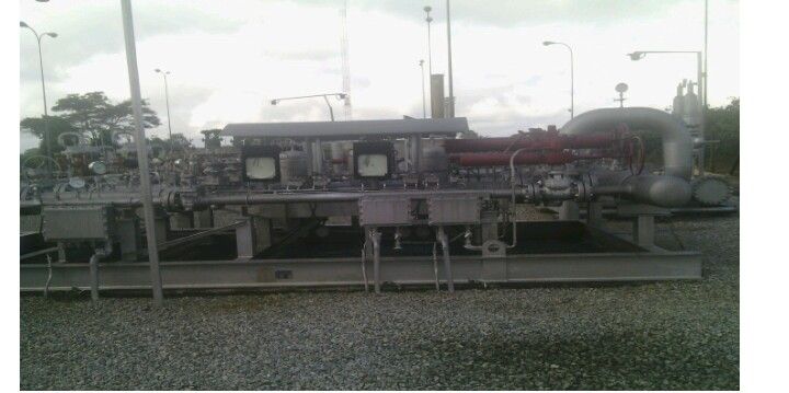
Plant/Pipeline Description
The Gas Plant is located at Onne in Eleme L.G.A of Rivers State, and was design with the capacity of 140mmscf/d (one hundred and forty million standard cubic feet per day). The primary source of gas supply to the station is the Shell Petroleum Development Company (SPDC) through a 114km underground pipeline network from the SPDC associated gas well in Okoloma to Alakiri, Eleme and Obigbo North respectively.
Its sole aim is to meter gas supplied to her customers by ensuring that:
- The gas is supplied to the customers is moisture (liquid) free.
- The gas is supplied at a recommended pressure and temperature specification.
- Daily accounting of the actual amount of gas supplied to the customers are calculated.
These can be achieved by the gas processing facilities installed in the metering station. The metering station supply gas to National Fertilizer Company (NAFCON) now NOTORE Chemical Industry
GAS PRESSURE AND TEMPERATURE: The gas is delivered to the station by SPDC at a maximum pressure of 60barg. The gas temperature at delivery points are:
Alakiri gas source: 38oc (38 degree Celsius)
Obigbo gas source: 47oc (47 degree Celsius)

Pipeline Description
The pipeline length is about 118.4km comprising two major segments which link all the gas sources into the same system.
SEGMENT 1: The starting point is Alakiri launching scraper trap station and end at Obigbo North Tie-in receiving trap station. The line diameter is 14” (14 inches) class 600 and the segment is about 37km, the first 19.7 km of the line runs parallel to the existing NGC Alakiri-Onne gas pipeline transverse mainly swamp area and crosses the Bonny River, Rivers state, Nigeria.
SEGMENT 2: The line diameter is 14ˮ (14 inches) class 600 and about 44km from Obigbo North Tie-in scraper trap station to the intermediate scraper trap station. The segment transverse predominantly dry terrain and crosses the following main features ; Imo River express road railway track pipelines and tarred road.

Major Facilities of the Plant
Inlet Pipeline
The inlet line is a 14”(14 inches) pipeline where the incoming Associated Gas (AG) from the source (SPDC) enters before onward circulation to other components in the plant. The line is connected directly with the pig line and equipped with two 14”(14 inches) motorized valves (MOV-201/202/204). 8” (8 inches) MOV-203 (manually operated valve)from drain, a pressure and temperature gauge.
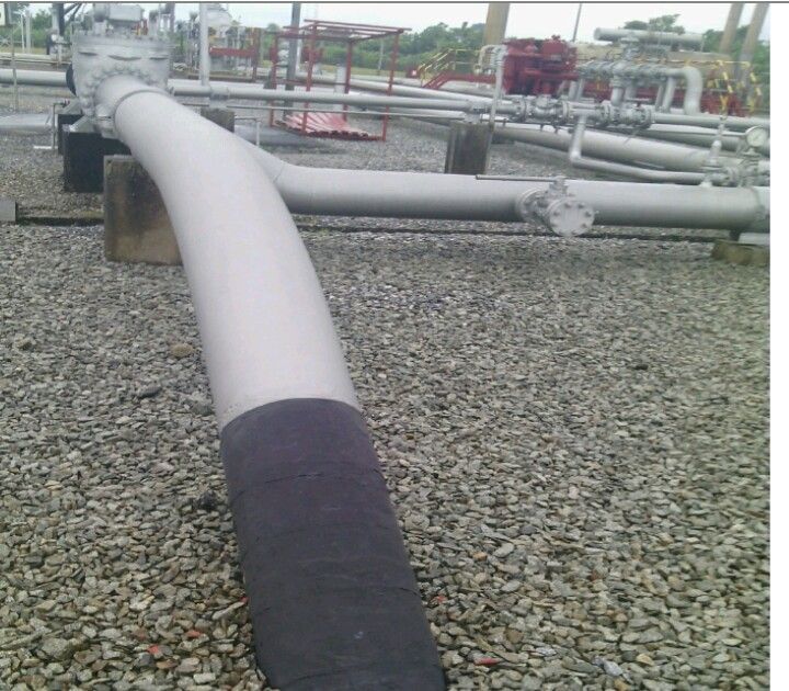
Inlet Pipeline

Receiving Scraper Trap (Pig Line)
The receiving trap is a mechanism designed to receive an incoming pig during pigging operation. It consists of a receiver barrel connected to the pipeline by series of valve that allows the trap to be in line with pipeline flow, vent drain thermal expansion safety valve and pig signaller (a field transmitter that relays the signal to the control panel as the pig approaches the trap).
Pigging in pipeline is a maintenance practice of using Pig Inspection Gauges (PIGs) to perform the operation of cleaning and inspection of the pipeline without stopping the flow of the product e.g. Gas, Oil etc in the pipeline. This is done by inserting the pig into a pig launcher and a differential pressure created within, before the launcher is closed and the pressure of the product is used to push the pig along inside the pipeline until it reaches the receiving trap.
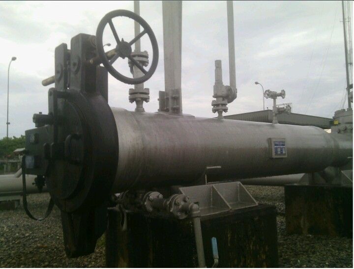
Receiving trap(Pig line)
Gas Scrubber (Filter Seperator)
The scrubber is another component in the station used for filtration and separation to further purify the gas.
Two "horizontal type" design are installed, one normally on stream and the other on standby.
The component operates on two stages of filtration; the first is the inlet stage which involves condensates/impurities coming with the gas got trap in the filter inside the inlet.
The second is the outlet stage where the condensate/impurities that might have bypass the first stage hints the baffle plate provided inside the outlet at a high pressure and sticks on, when accumulated on a continuous process fall off to the bottom chamber before being transferred to the condensate tank.
The gas scrubber has the following sections:
- Centrifugal inlet device: where the primary separation process takes place.
- Settling section: that reduces the turbulence of fluid stream and allows the liquid droplets to fall to the bottom of the equipment.
- Mist eliminator: to eliminate small liquid droplet that did not settle.
Other components on the scrubber are the level control switch(valve), liquid dump valve, gas back pressure and relief valves, pressure gauge, sight glass, instrument gas regulator and piping.
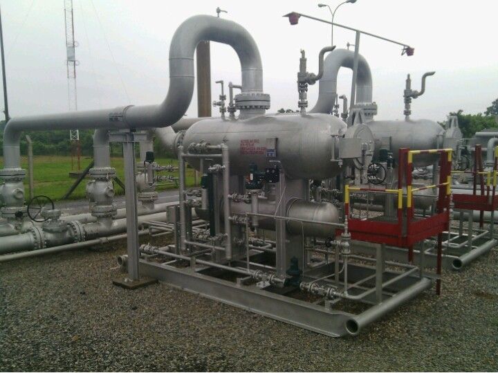
Gas scrubber (filter separator)
Gas Heater
This instrument as the name implies is designed to heat gas to avoid the formation of hydrate, liquid hydrocarbon, and water due to pressure reduction and also to raise the temperature of the gas above dew point at normal operating condition and maximum flow.
Two indirect type fired gas heaters (101/102) are installed in the station. This type of heater uses a means of water-glycol mixture (to prevent corrosion of the bath within the heater shell) for heat transmission (thermal exchanger) generated by the burners and absorbed by the gas without direct contact with the incoming gas to avoid explosion.
The heater consists of mainly a receiver where the burners (flame tube) and the gas coil (where the gas to be heated flows through) are set, the expansion section where the expanded heat from the heated water/glycol bath flows into, and the heater insulated shell that provides the enclosure to the other components within.
The design of the flame tubes liberate heat in two separate chambers (stacks) which allows for a rapid heat transfer (by radiation and convection) from the burners to the water/glycol bath. The heat is then transferred from the bath to the gas coil and safely to the gas going out via the outlet of the heater to the reduction skid.
The basic operation of the heater depends on the continuous supply of fuel gas the burners which are drawn off downstream of the heat itself.
The heater is equipped with upstream and downstream gas operated shut-off manually operated valves (MOV-201A/201B/202A/202B) which can be operated from the field or control room and automatic shutdown that can occur in case of the following: absence of flame (BS), low water level (LSL), high water temperature (TSH), fuel gas low pressure (PSL), fuel gas high pressure (PSH).
Local temperature and pressure indicators are also provided upstream and downstream of the heater.
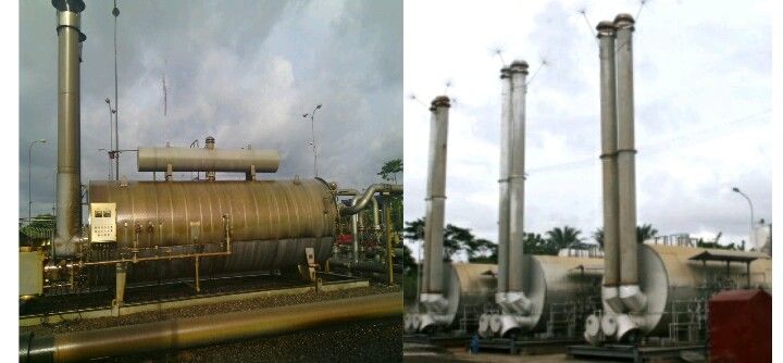
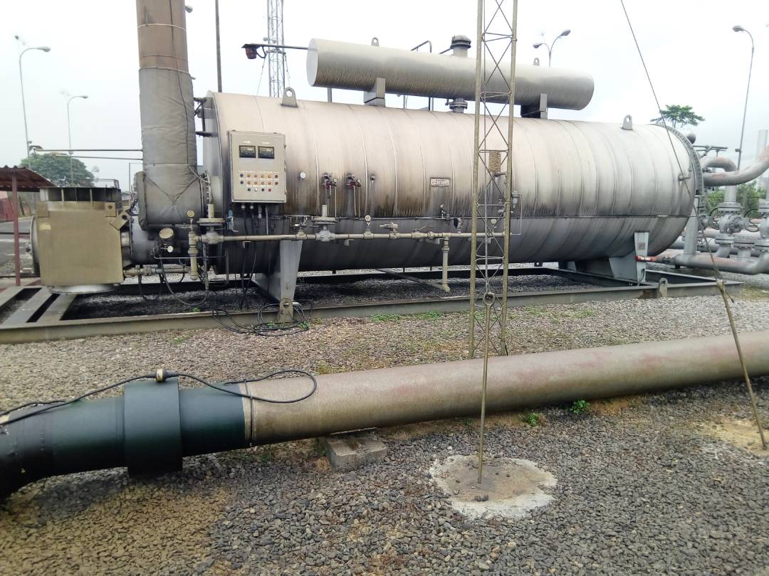
Indirect fired gas heaters

Pressure Reduction Skid
The pressure reduction skid is a system for reducing the pressure (force) that comes from heater to a particular set point 44barg. It consists of two control valves.
One control valve on the skid is always on stream(active) at a time and the other on standby(monitor). Each of the line consists of an active and monitor valve with pressure gauge on it. The active valve is normally open at a designated set point of 30barg of pressure and the monitor valve monitors the output flow stream of active, but only comes up at a set point of 32barg of pressure to compensate the active, implying the active valve fails (fail open). When this occurs, the incoming gas flow pressure equals the gas output pressure and the monitor valve closes completely preventing gas flowing to the rest of the system and invariably to the customers as their design capacity may not be able to handle such high pressure to avoid equipment damages.
Alarm and safety system are to come up during the following emergencies: high pressure alarm, and high-high pressure alarm.
Self control pressure relief and pressure safety valves, high and low pressure vent valves open automatically or when initiated emergency station shutdown (ESD) to completely vent the gas.
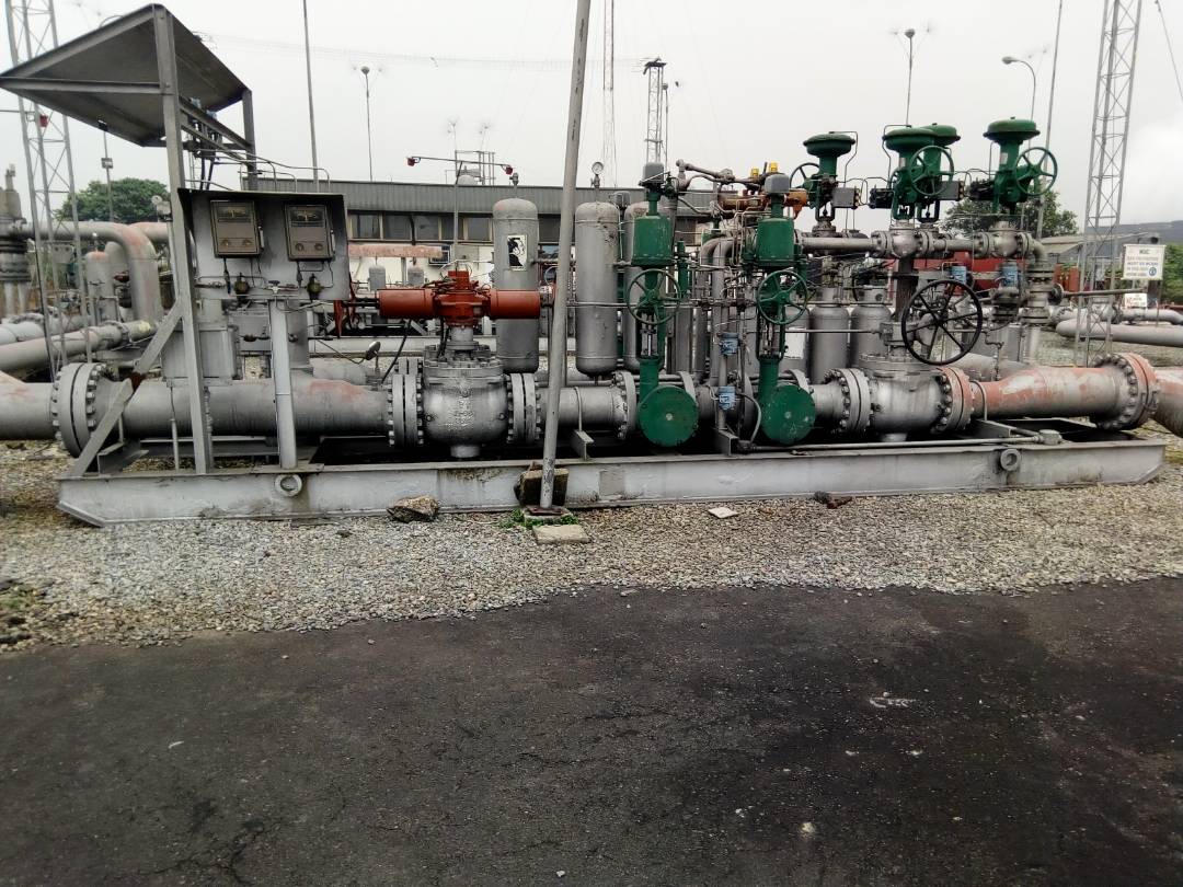
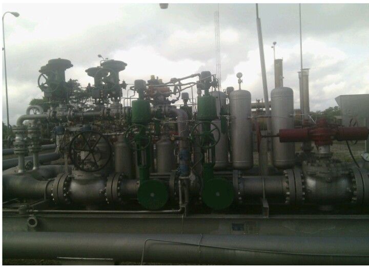
Pressure Reduction Skid

Metering line/skid
The metering line is where the gas is metered out to the customers.
Four identical metering lines are installed in the station, each designed with the capacity of 140MMSCF/D in accordance with the American Gas Association (AGA) specification. The metering comprises of a two 4"(4 inches)line (Run1 & 4) and a two 8"(8 inches)line(Run 2 & 3).
The Gas is measured through one of the metering line, the lines consists of operated shutoff valves upstream/downstream of the metering system controlled by the metering control system and motorized valves installed on each line.
This skid is completed with the "Daniel Orifice meter" fitting to effectively extrapolate parameters such as the Differential pressure (DP) and the Static pressure(PF) of the incoming gas.
The lines are equipped with the following for each meter run: Mechanical circular chart, three pens recorder (differential pressure, temperature & static pressure), pulsating dampners, electronic flow transmitters (FT) low & high range, electronic pressure transmitters (PT) and electronic temperature transmitters (TT).
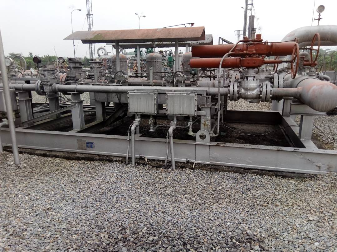
Metering skid
Main Control Panel/System
The station uses "Daniels model mimic" control panel located inside the control room to perform its operations.
The system works in connection with components such as:
The martially panel/cabinet which provides the needed interface between the field parameters and the main control.
This panel is equipped with the "Allen Bradley programmable logic controls (PLCs)"and relays for effective and efficient interpretation/transmission of instructions
from the field parameters or initiated from the mimic panel.
Alarm panel that comes up when any fault or abnormal condition is detected to alert the operator around for necessary actions to be initiated.
Heater panel that provides the link between the heater field parameters and control panel and can also be used to operate the component from the control room.
The mimic panel consists of control buttons for all valves and necessary components in the field, the four metering recorders and flow computers, gas chromatograph control (AT-201), gas chromatograph recorder (AR-201). Various alarm indicators buttons for station normal emergency shutdown, and controllers for other necessary field components.
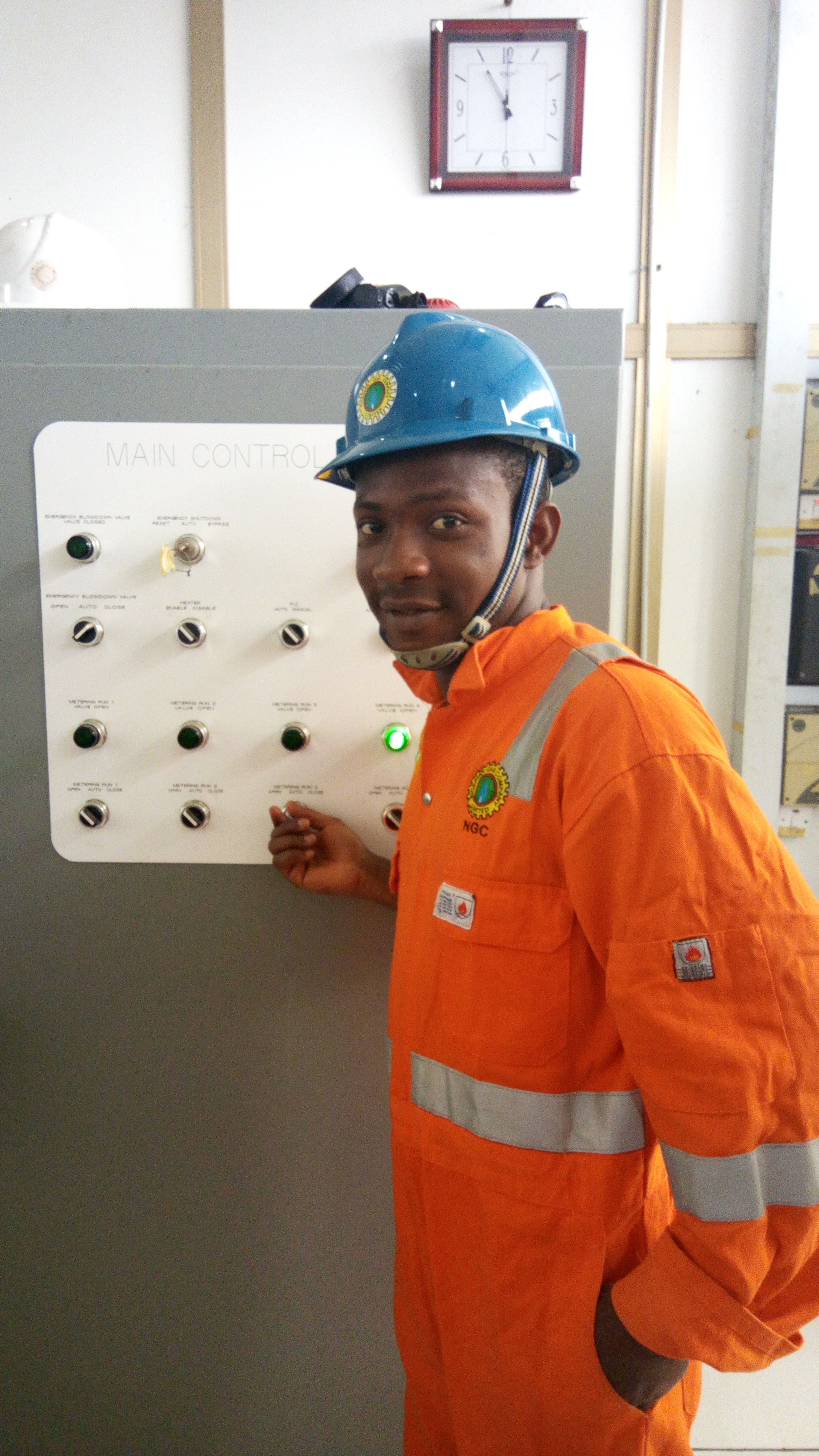
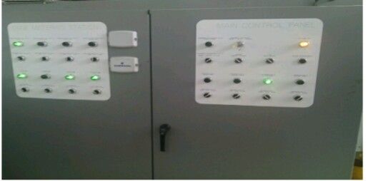
Main control panel/system
Instrument and Actuator Gas Supply system
The metering station also has an instrument gas supply line which supply gas to actuators to enable the operations of opening and closing of actuator operated valves. This system receives its natural gas upstream from the motorized valve (MOV 204) and downstream of the pressure regulating system. This system has two miniature scrubber/gas filter separator one operating and the other on stand-by, it is also equipped with miniature pressure reduction skid, vents, drains, pressure safety valves, level indicators and pressure drop indicator. Actuator gas is sent directly to the motorized valves while instrument gas pressure is reduced to 7barg by means of a suitable pressure reducing system branch line is drawn for supplying fuel gas to the pilot burner of the heater.
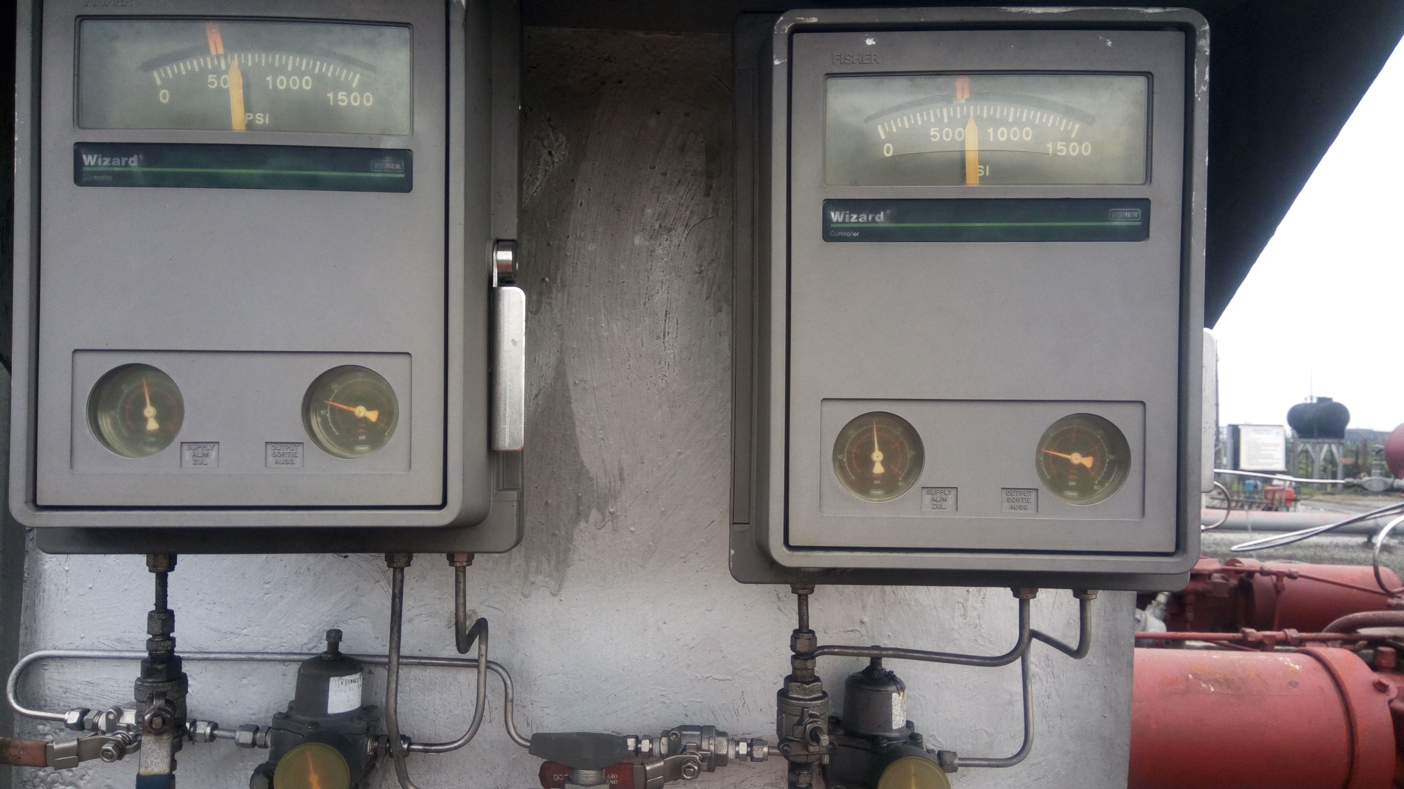
Pressure controller guage
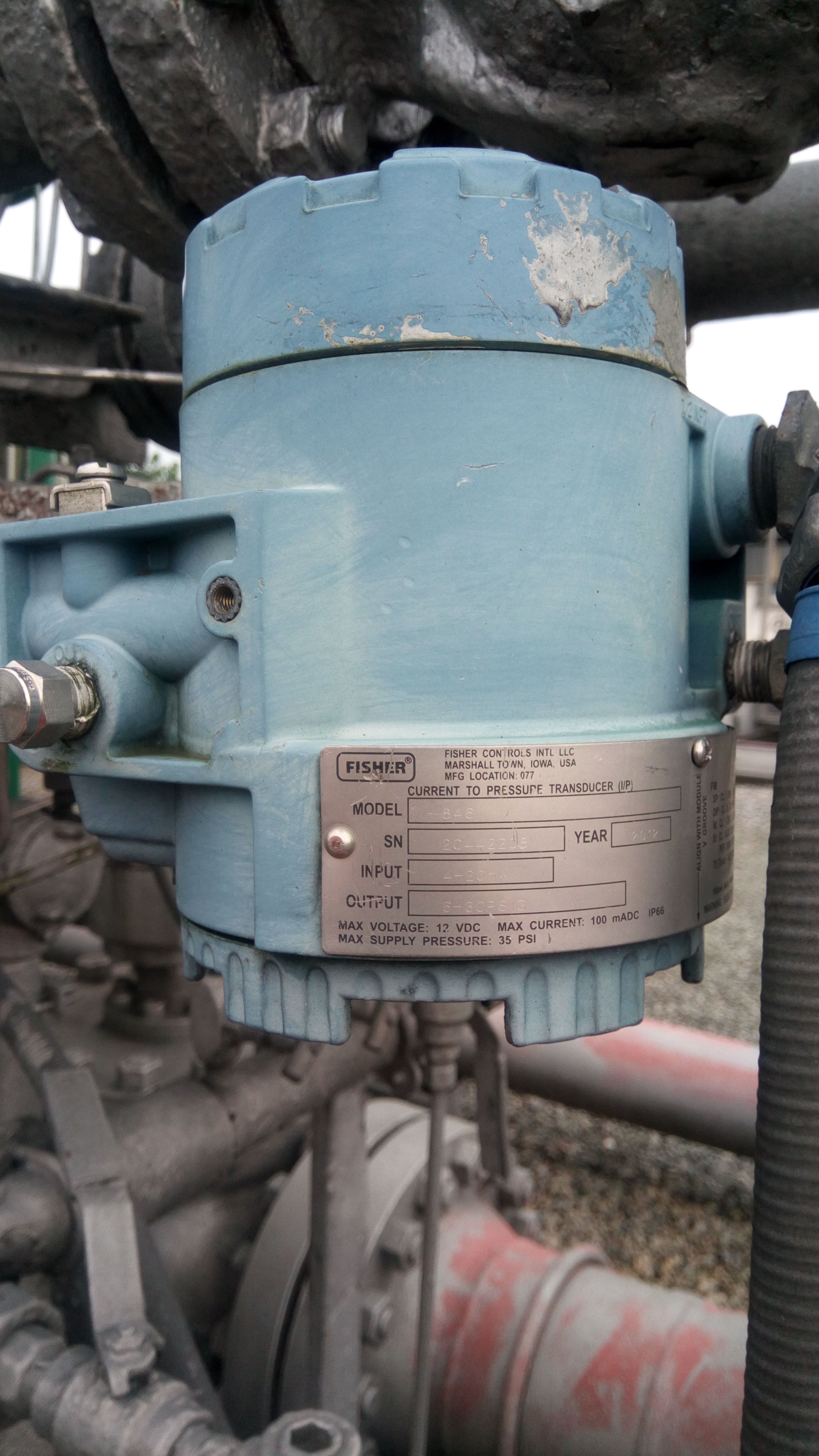
Pressure Transducer
The gas goes through the processes above before being transported to the customer. This processes described above is the most exciting part of Petroleum engineering.
I hope this post was able to enlighten those that were in the dark about the industrial processing of natural gas.
All images and texts are original works of @profsam. Phone cameras and pro cameras are highly prohibited on the facility for safety reasons so all images were taken with a "Safety camera". Cheers!!...to yha'll..Thanks..

Quite detailed Prof. Your garnered enough experience working there. I've fear for gas plants, I hope I get an opportunity to work in one someday
oh..hh.. thanks..i'm glad you liked it..
.....i mean, why should a project report go to waste when it can generate SBD 😉
yeah..
Hi 'Sam, I must say yiu've gotten a full fledged educative material on here. I enjoyed understanding all the process as you highlighted.
I remember once visiting a bank branch at the Eleme Pretrochemical station for a proposed renovation work. We were told during the site reconnaissance that they do not have any alternative power source apart from the national grid (which obviously is being supplied by the petrochemical company). It was really strange to find a bank branch with no generator nor an inverter(can't remember if they even had a UPS).
Steem on Sam
@dorth
Thank you sir..i'm glad you liked but you didn't upvote the post??..
sam, try editing your tags. include steemstem or stemng as your tag.
Thanks.. I have done that
You have really acquired knowledge. Nice one.
Yeah...enough vital knowledge..thanks for commenting
WARNING - The message you received from @gordonramsay is a CONFIRMED SCAM! DO NOT FOLLOW the instruction in the memo! For more information, read this post: https://steemit.com/steemit/@arcange/scammer-reported-steemitrobot
Get your post resteemed over 90000+ followers and get upto $21+ value Upvote. Your post will skyrocket and give you maximum exposer.
See our all pakages at: https://tinyurl.com/whaleboostup