#Electronic basics 3 Resistors
TAKE A STANCE - A RESIST STANCE
A JOURNEY INTO THE WORLD OF RESISTORS
Ok i promise no more silly word play geezz can't a guy try and put some ice on the block.
Source memegenerator.net
Okay enough chit chat lets get straight into the business today we are gonna be talking about resistors and today as with all posts we would look at all parts from color codes to types of resistors and the works. I would also like to mention that this is the first of two on resistors so be sure to check out my other post on Resistors let's get started.
WHAT IS RESISTANCE
I know that's the million dollar question. Well you can check out my previous post on other general terms used in basic electronics Blog post 1. But for the purpose of this post we will still define it again , more of a summary.
Well resistance basically it is the ability of an electronic material or tool to oppose the flow of current or voltage in a given circuit to a give point. And well to be honest all electronic tools from capacitors to inductors and even ic's all have resistance no matter how small the value is. And sometimes some circuits actually depend on these little resistance to form a great part of the overall circuit.
Also talking about resistance it is good to note that when ever a current passes a resistance a corresponding potential difference is set up giving rise to the famous ohms law basically
V=IR
Also people lets clear something up here the above only holds true for DC circuits it doesn't hold true for AC circuits, those have the problem of reactance and impedance to deal with. Its also good to note that its unit is in ohms and it is designated by the greek symbol "omega"
RESISTORS
Now we are finally made it past the yellow brick road and we are here at resistorville.
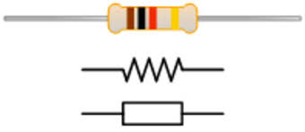
In an electronic circuit we have fun small but powerful materials that we use to create resistance or voltage drops called resistors. They have a symbol as shown
Another thing to note is that the symbol usually varies from country to country. But those are the basic symbol used generally.
Now if you notice from above you see a multi-coloured piece of material. That beauty my friends is the common SMD resistor that is seen around and we would be making use of so basically using secretly known code ( its not really a secret) that were taught up the international standard IEC 60062. We can decipher the value of the resistor and its general tolerance (maximum resistance it can handle before burning out)
This leads us to-
##RESISTOR COLOR CODE
Basically on a given resistor there are 4-5 color bands
Now note carefully for a 4 color band system
*There is no specified direction that is followed when reading a resistor but usually the first band is closer to one of the leads and the gold or silver band is usually the last bands to be read
*The first two bands usually repersents the value of the resistor
*The third band represents the multiplier
*The last band usually represents the tolerance of the resistor
Basically let's see the table for the resistor color code and value for each color
Ok then know the above lets apply them in real life operations :
If the first color is RED ,second is RED ,third is BLACK and the last is SILVER it means taking from the above RED is 2, the black is 0 i.e. 10^0 = 1 and also the last band being the tolerance band that is silver 10% therefore the value of the resistor is, yep you guessed it, 22ohms with a tolerance of 10% i.e ( 22*1)
You can try various examples using other SMD resistors and all
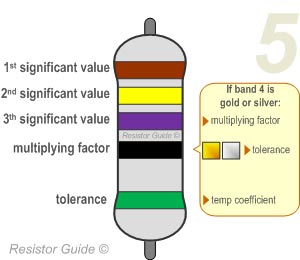
Also for a 5 band the rules are basically the same the only difference is that you have another extra band added to the first 2 bands to give a more accurate reading for the resistor. And also you could also make use of your multimeter to measure the actual value of the resistor.
View the image below for a clearer understanding
Source resistorguide.com
RESISTOR TYPES
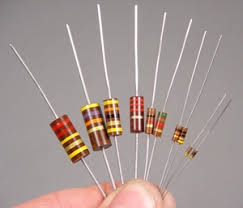
The resistors that we have been talking about are called SMD resistors or surface mounted resistors
Now there are two classes (i want to classify them as such for the purpose of simplicity). They are:
I. According to material that is used to make them
2.According to materials that we are actually use
Now according to the material that is used we have:
1.Carbon Composition Resistors
2.Wire Wound Resistors
3.Thin Film Resistors
5.Thick Film Resistors
6.Carbon Film resistors
Now generally the above type materials are used to construct fixed and variable resistors. To learn more about this visit resistor types
Now according to the ones we are going to use we have :
1.Fixed resistors
2.Variable resistors
They are used to vary the over a resistive surface using a dial or knob
They are very good for applications that don't involve a fixed value of resistance like in the case of the radio that makes use of the variable resistor either as a tuner or as a volume controller.
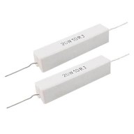
They are basically as the name suggests used for high power applications. They are usually used in circuits that involve large amounts of current. They also have a least wattage of 5 watts and an example use for power resistors are load banks used to dissipate power generated during engine braking in vehicles using electrical motors, such as locomotives or trams.
Basically they are not very much resistors used in basic electronic projects.
Well that's all for today stay tuned for the second part of the resistor series where we cover basic calculations and all
Hope you enjoyed your tour of resistorville. No refunds by the way.
I would also like to know what problems you have faced with resistors do well to leave it on the comments below
Stay creative resteem upvote and comment, till the next post.
Sources http://www.resistorguide.com/resistor-color-code/
Google images
http://www.resistorguide.com/power-resistor/
wwww.resistorguide .com
.jpeg)
.jpeg)
.jpeg)
.png)

.jpeg)
%20(1).jpg)
Congratulations! This post has been upvoted from the communal account, @minnowsupport, by chinedu101 from the Minnow Support Project. It's a witness project run by aggroed, ausbitbank, teamsteem, theprophet0, someguy123, neoxian, followbtcnews, and netuoso. The goal is to help Steemit grow by supporting Minnows. Please find us at the Peace, Abundance, and Liberty Network (PALnet) Discord Channel. It's a completely public and open space to all members of the Steemit community who voluntarily choose to be there.
If you would like to delegate to the Minnow Support Project you can do so by clicking on the following links: 50SP, 100SP, 250SP, 500SP, 1000SP, 5000SP.
Be sure to leave at least 50SP undelegated on your account.
High power resistors can be used as so-called current shunts. Shunts can be used to measure current in a circuit precisely and with an op-amp - you can read the current on an Arduino or on other MCUs.
Thanks for ur contribution