THE POWER SAW EXHUSTED.. WITH HD IMAGES!!
Today on my ‘Engineering photography series’ I am going to be detailing on the klaeger power hack saw. I had the pictures taken in my schools workshop yesterday.
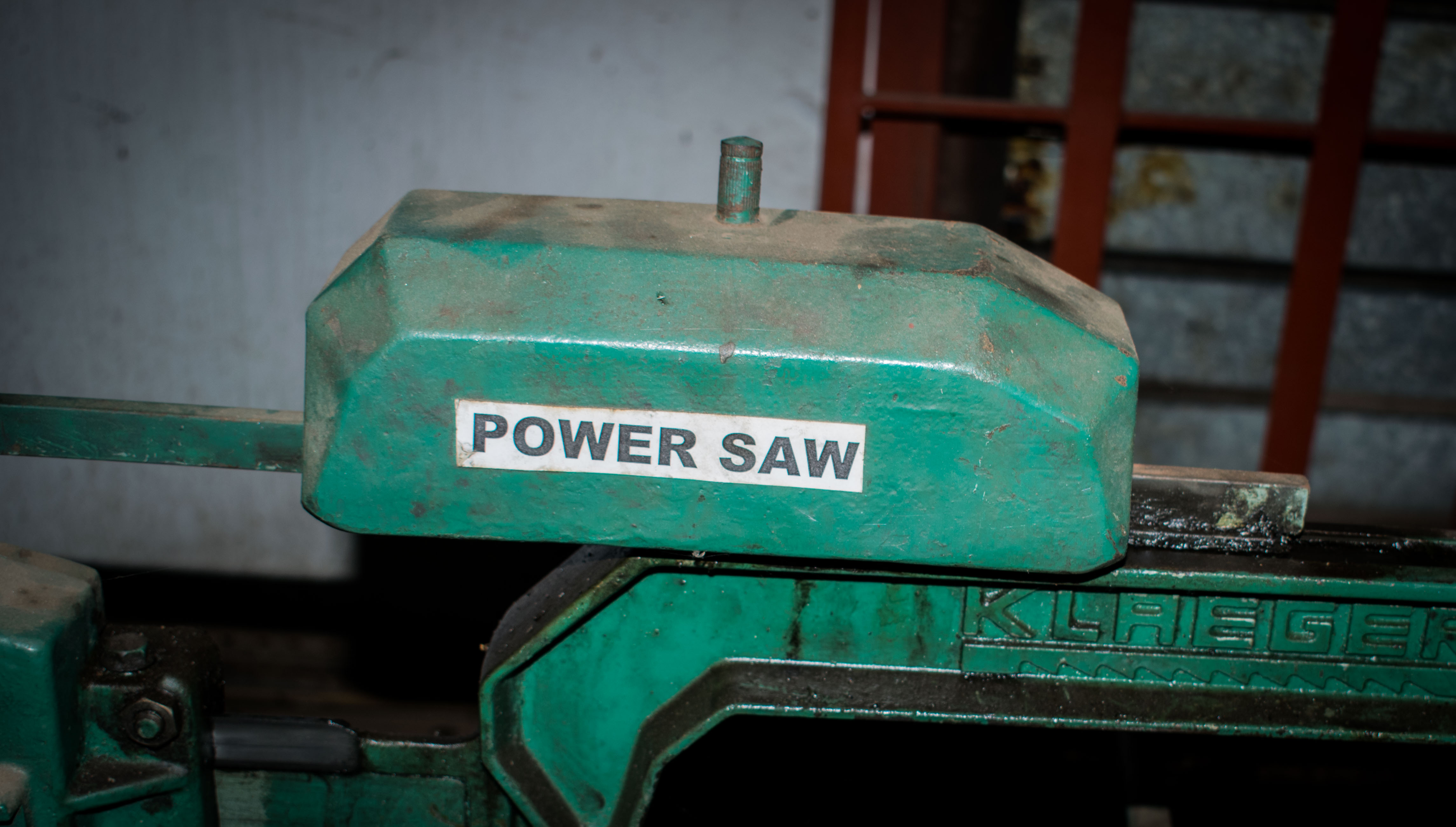
The power saw
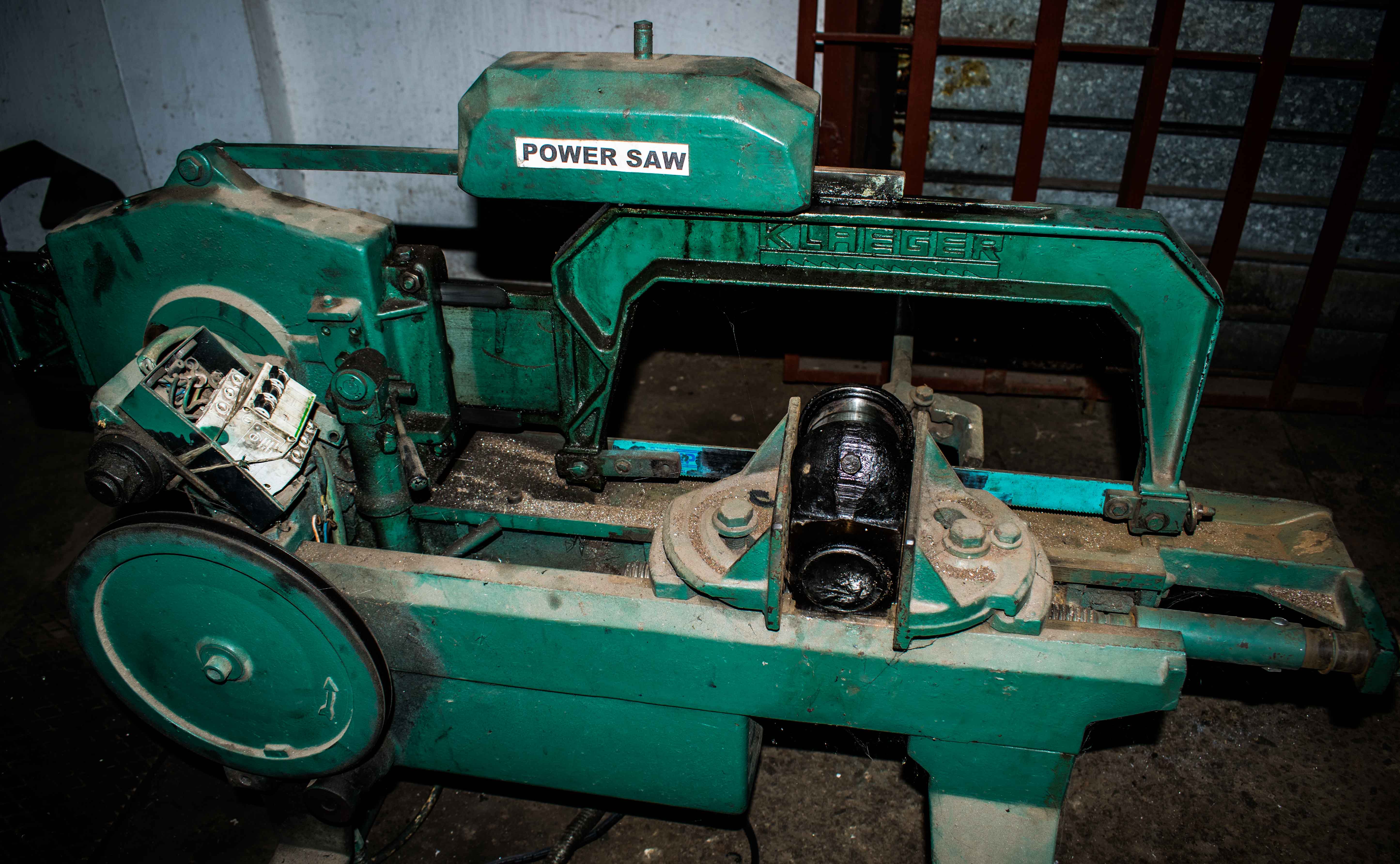
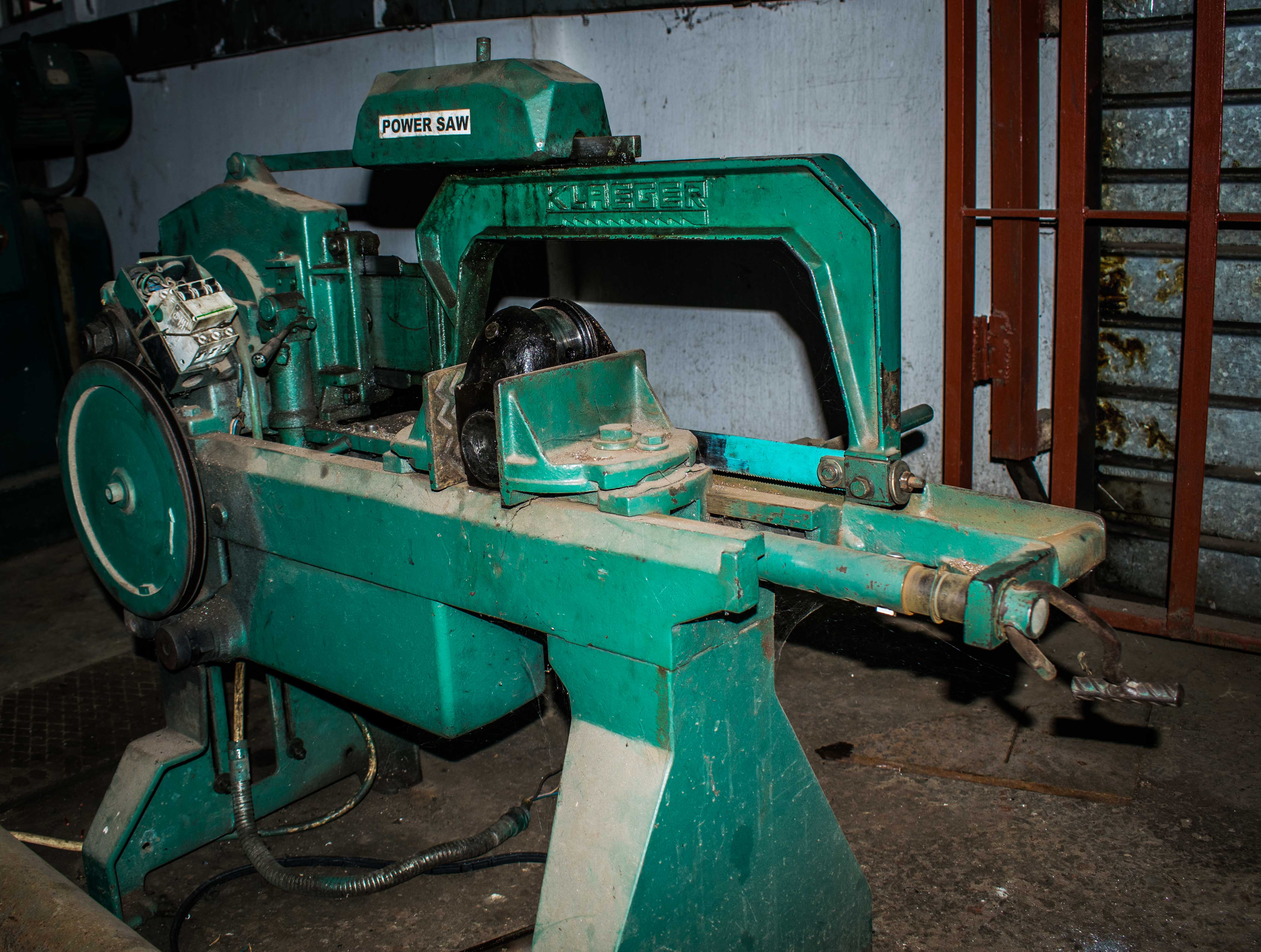
The power saw is a machine that makes use of an electric motor. It is designed for cutting large metals of more than 15mm thickness. It comprises of various components that help achieve the desired cutting. They are designed with specific horse power (hp) motors such that the maximum speed of cutting in various saws vary for different designs. The electric motor in this design works with a relatively medium cutting speed and is designed to undergo a to and fro movement during cutting.
Being a rather complex design compared to that of simple hack saws, the power saw is designed with various parts:
The vice
The switch
The gear mechanism
The saw arm and blade
The dead weight
The flywheel
The base/support
Each part is designed to specification to allow easy, fast and efficient metal cutting.
Let’s take a look at each part:
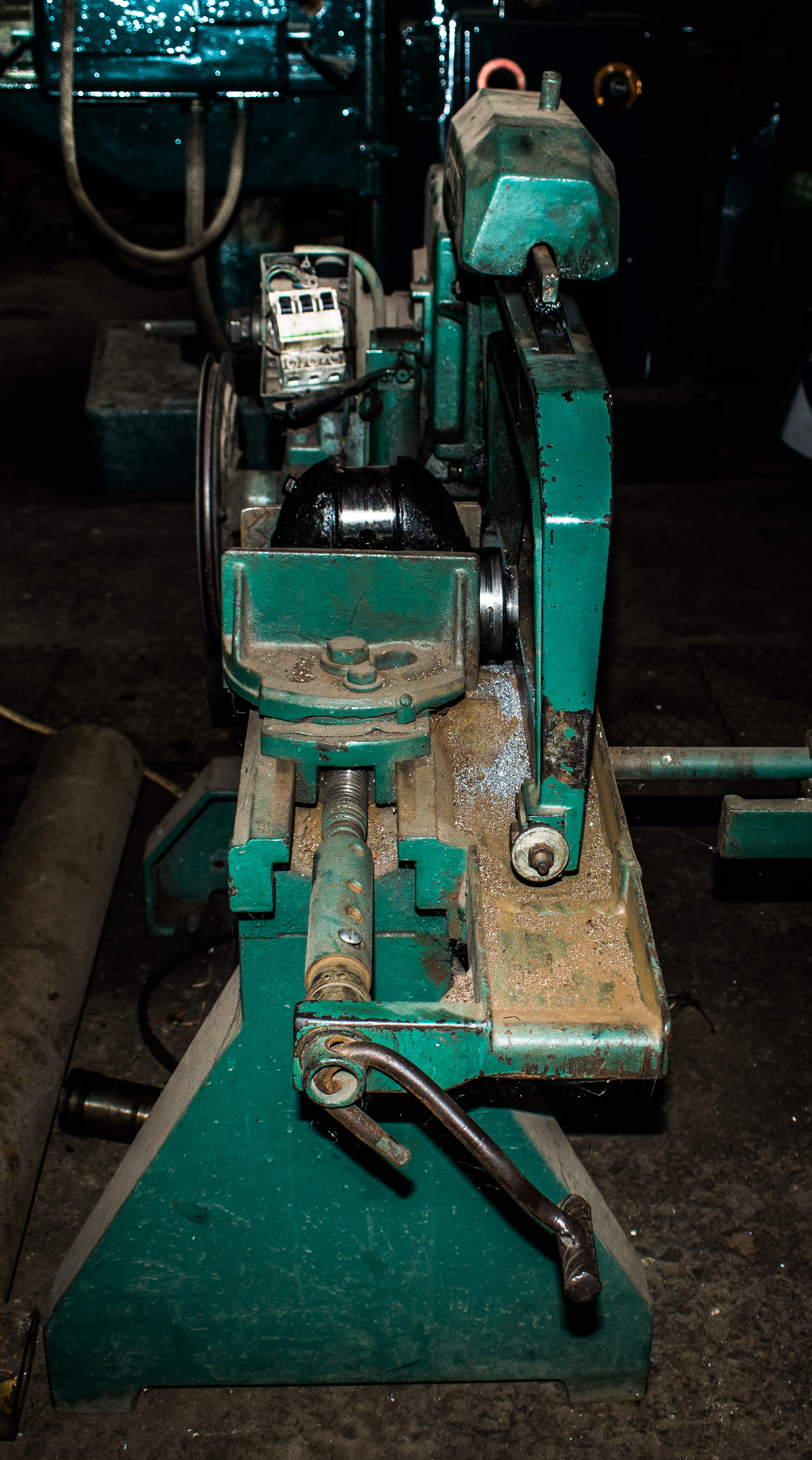
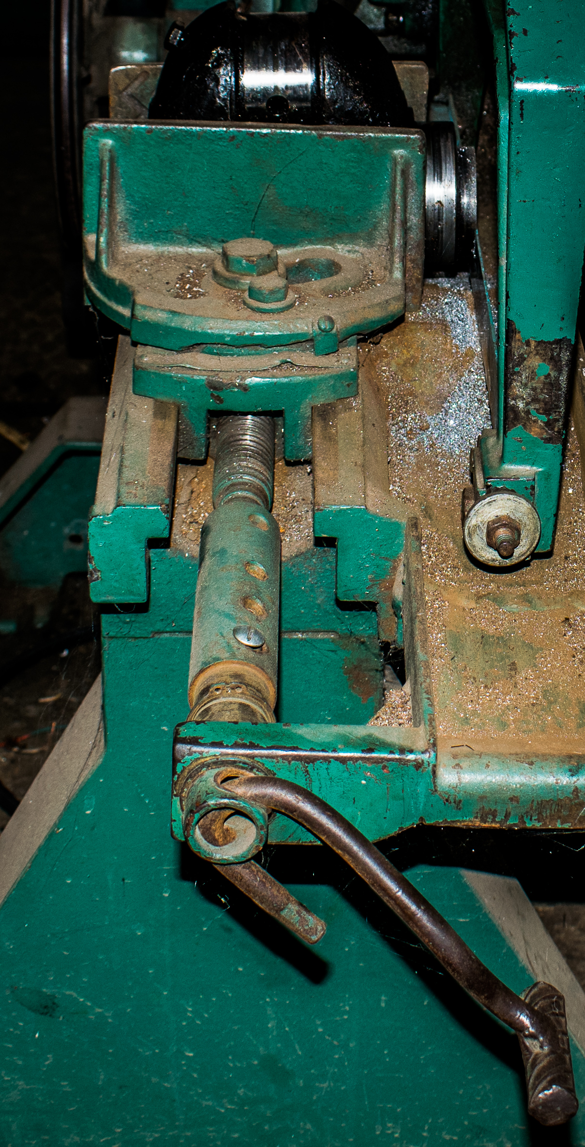
The vice
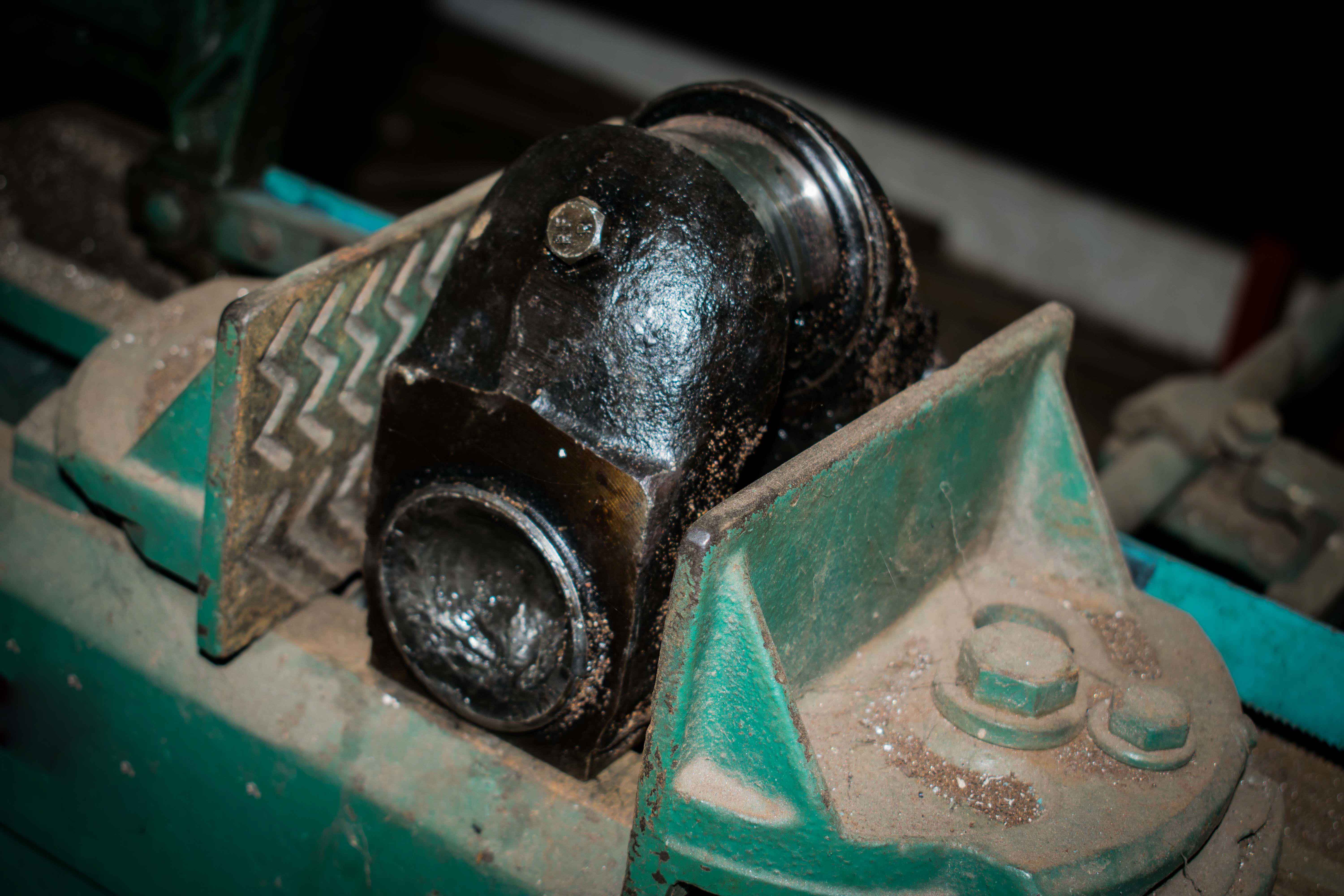
The power saw vice serves the purpose of holding metals to be cut firmly in place.
It is designed as a clamp that close up when the vice handle is tightened (rotated clockwise) and opens up when the handle is rotated in the counter clockwise direction. The interior of the vice is rough. A design to aid firmer clamping.
The switch
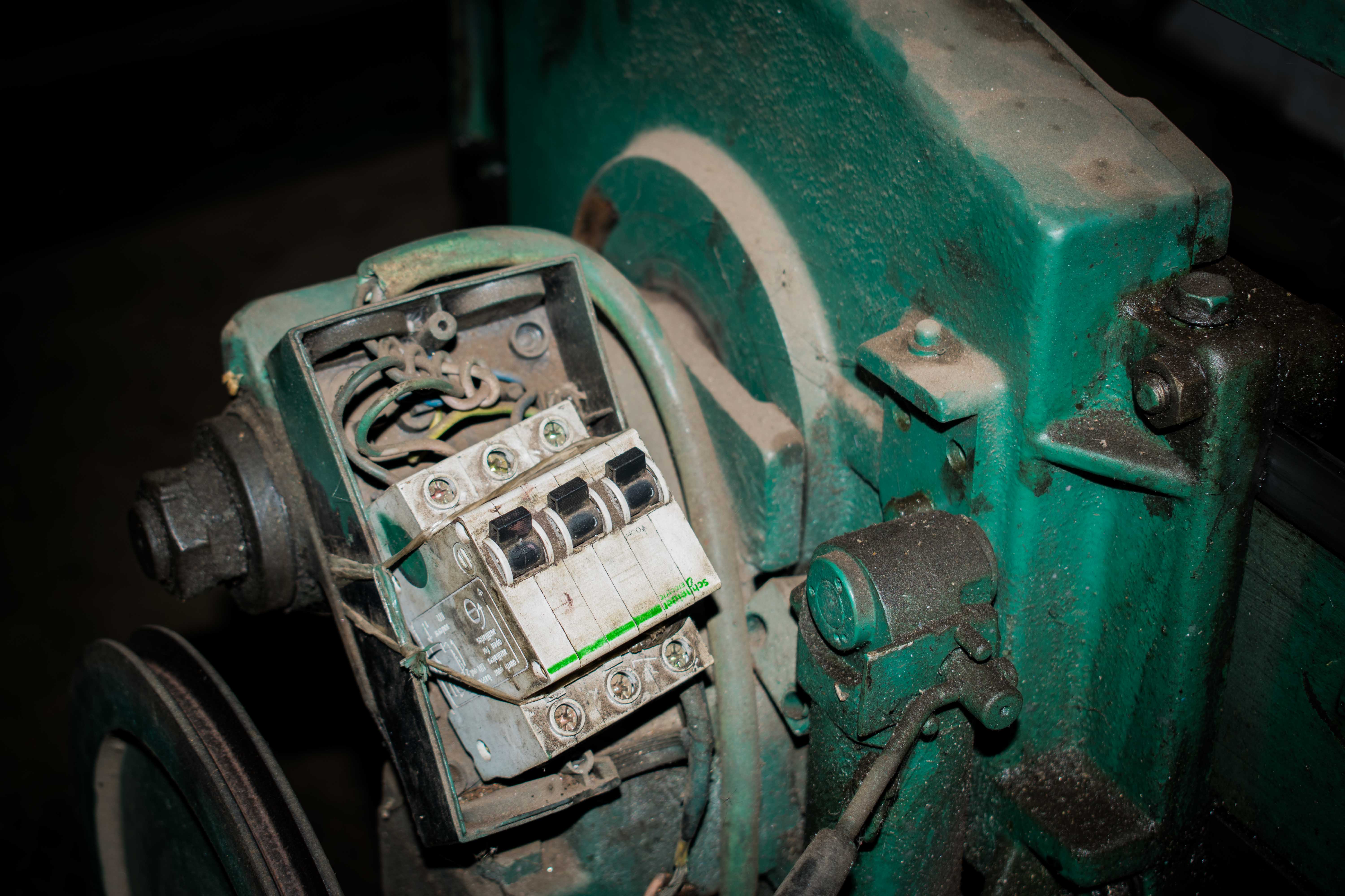
While some power saws make use of three way switches, the switch design here is that of separated switches. From left to right, the first switch is used to turn ON the electric motor, the next switch turns ON and adjust speed of the mechanism that moves the saw arm to and fro. The last switch from the same direction disengages all two switches (that is… turns off the other two switches). It is more or less a safety switch.
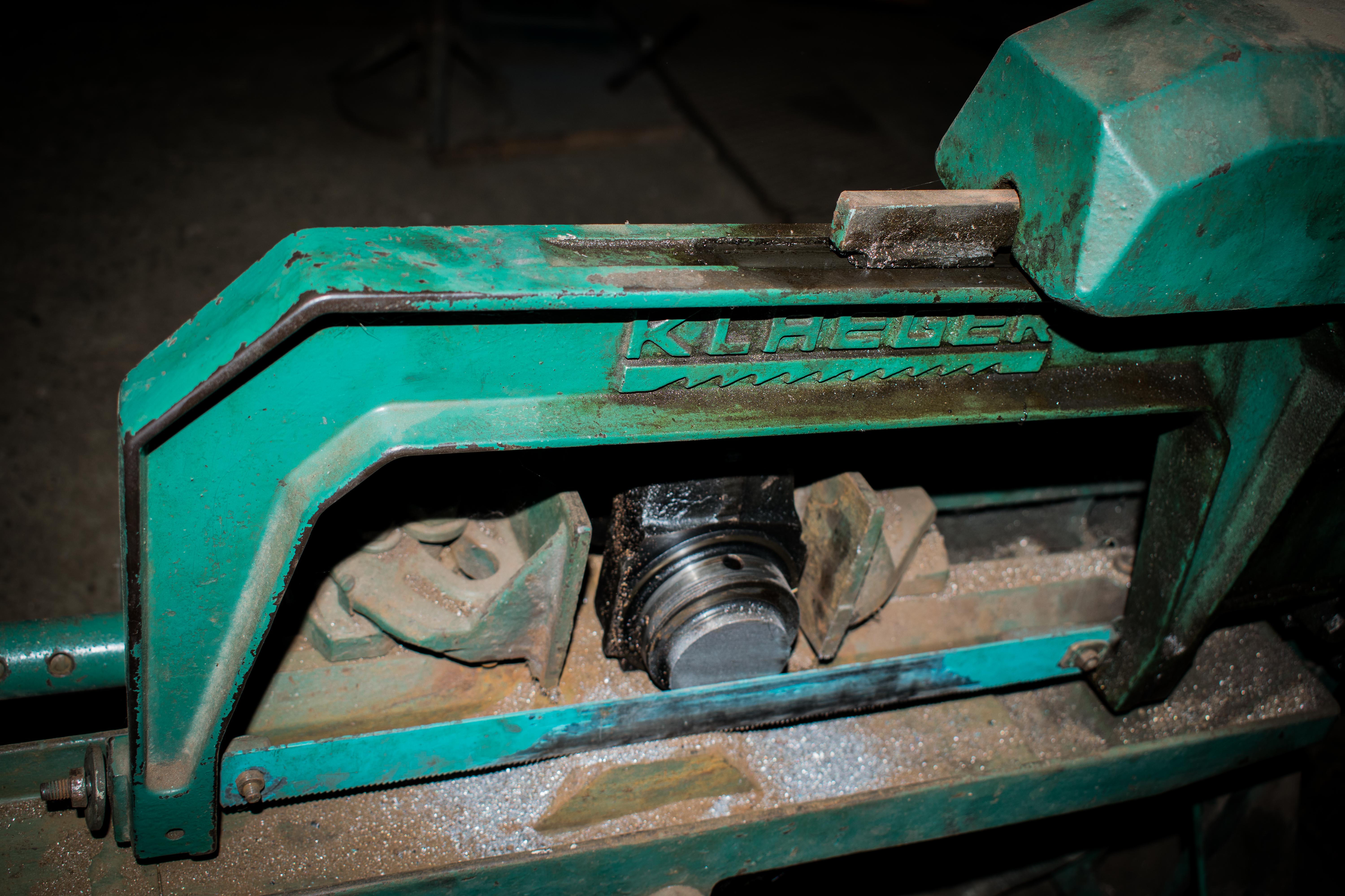
The gear mechanism
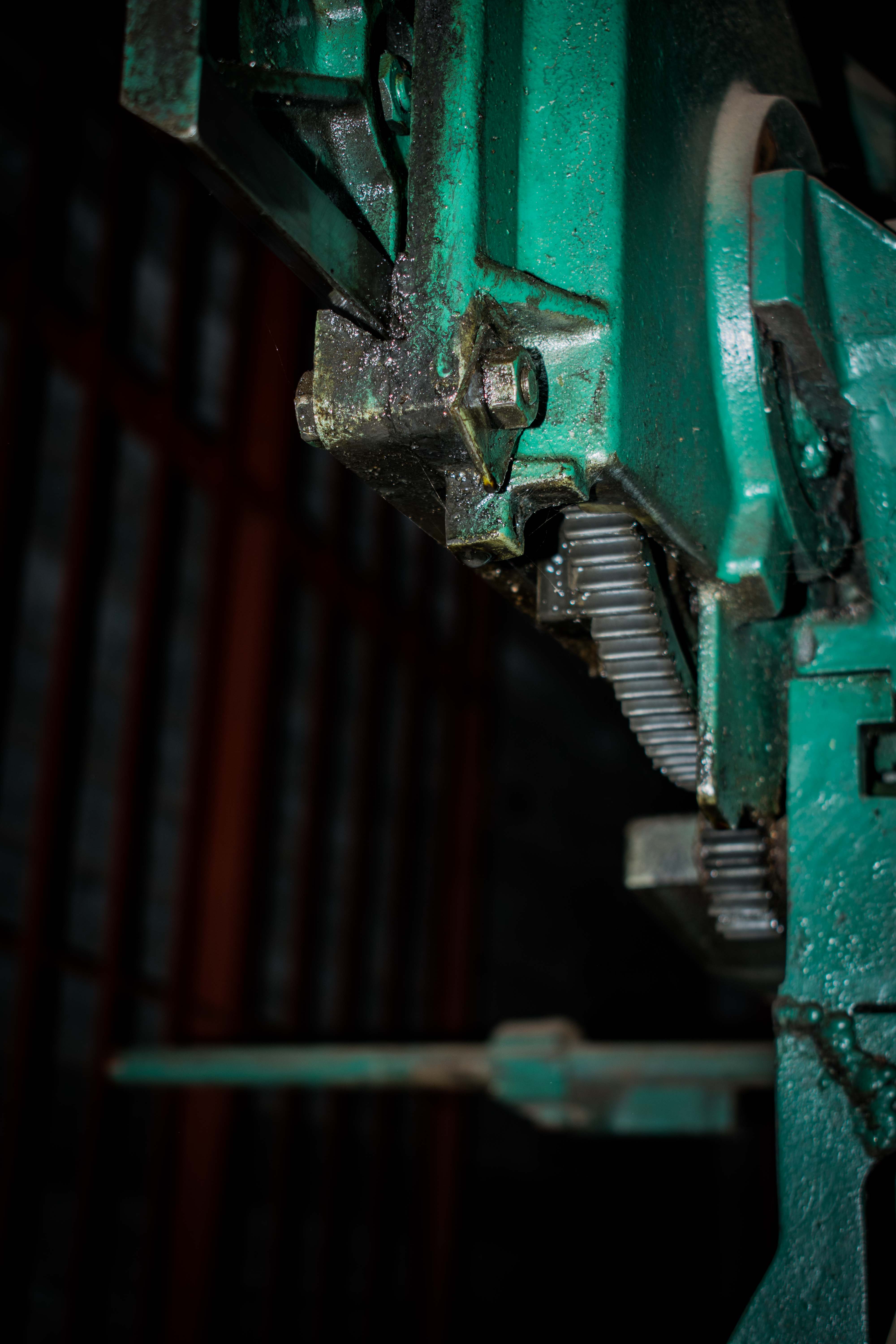
The gear mechanism of the power saw is designed to help the electric motor. It does this by reducing the R.P.M (revolutions per minute) of the arm movement. This is to accommodate the design that the arm of the saw must not run at the same speed of the electric motor. It could result in overheating between the metal to be cut and the blades of the saw. Such high speed could spell disaster.
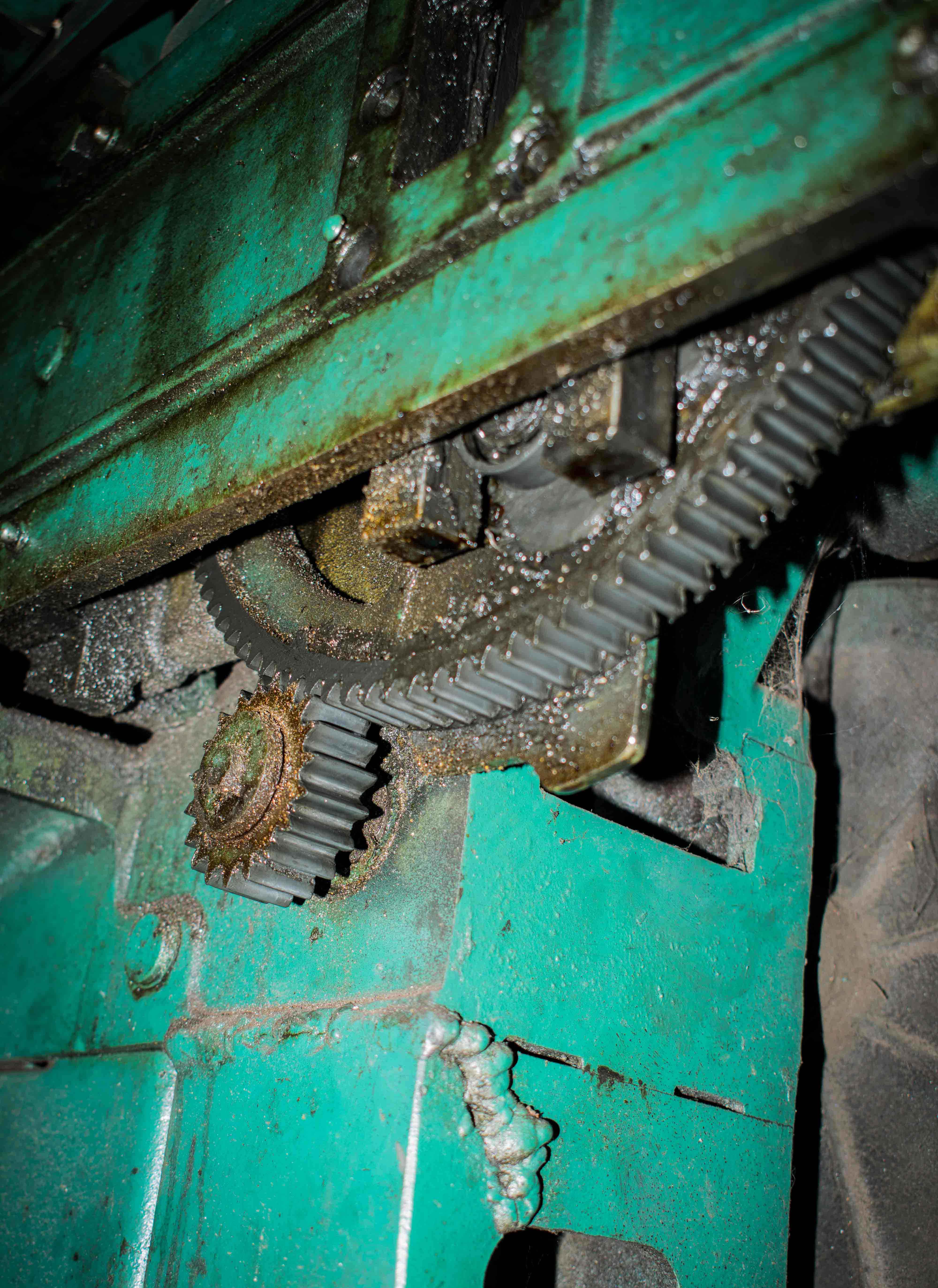
The small gear is connected to the electric motor. The electric motor rotates the small gear and the rotation is transferred to the large gear. Due to the difference in gear circumference, a complete rotation of the small gear will result in only about one sixth (1/6) of the large gear rotation. This in turn means that the electric motor has to undergo about six (6) forward rotations before the saw arm will do a complete forward movement. Another six (6) backward rotation of the electric motor similarly results in the complete backward movement of the saw arm, meaning a complete to and fro cutting motion.
The motor of the saw is covered just beside the gear mechanism.
The saw arm and blade
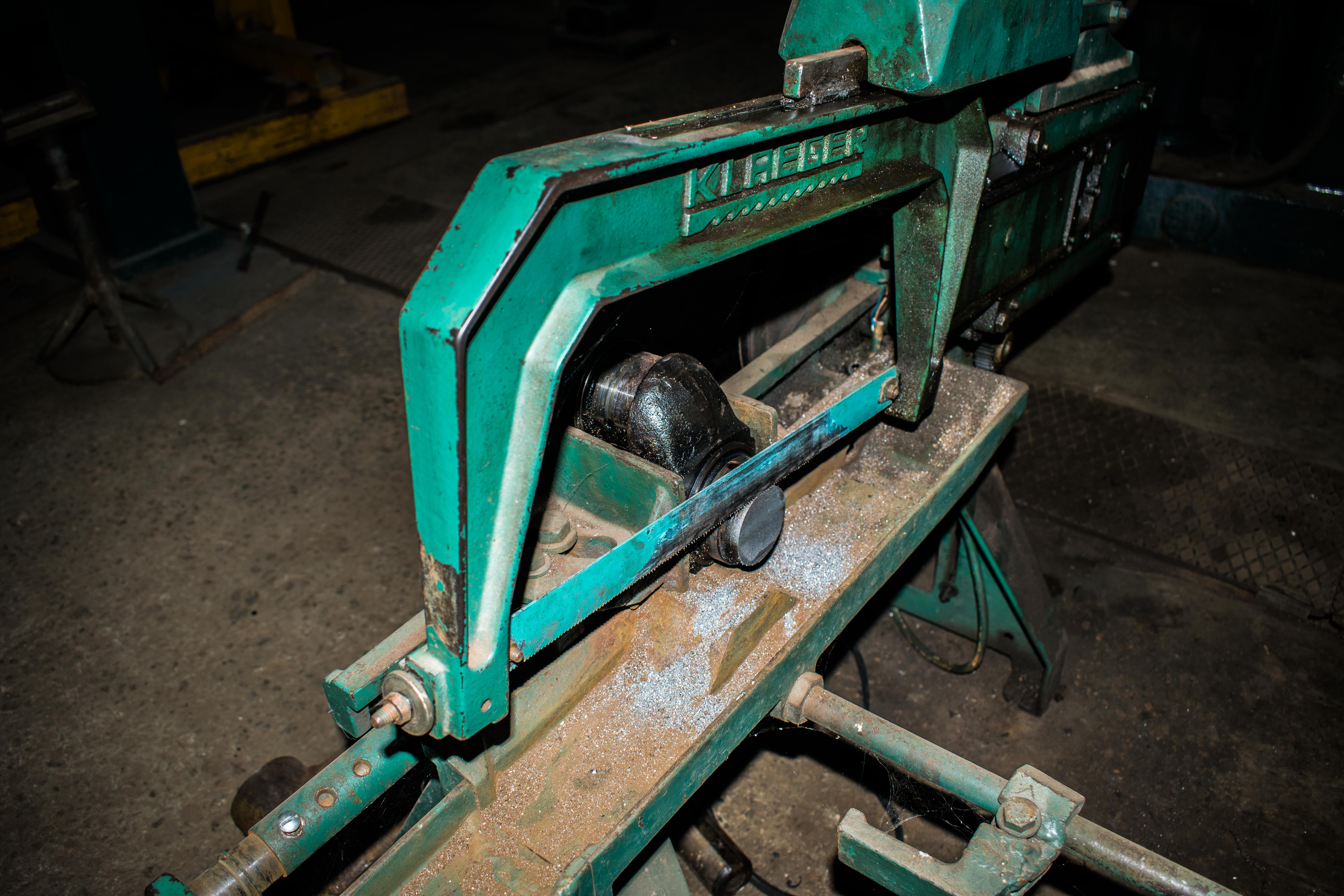
The saw arm and blade are designed to work together with the dead weight. The saw arm holds the cutting blade intact and is responsible for transferring the to and fro movement from the gear mechanism to the blade and unto the workpiece (metal to be cut). The blade teeth also points towards the left of the arm for better and efficient cutting as earlier stated in my previous post on ‘engineering photography series’.
The dead weight
The dead weight of the power saw is designed to apply a downward cutting force in addition to the overall weight of the saw arm. The downward cutting force is what is responsible for the continuous cutting. Cutting to and fro motion may just be ‘machine dancing’ without this downward cutting force.
The Flywheel
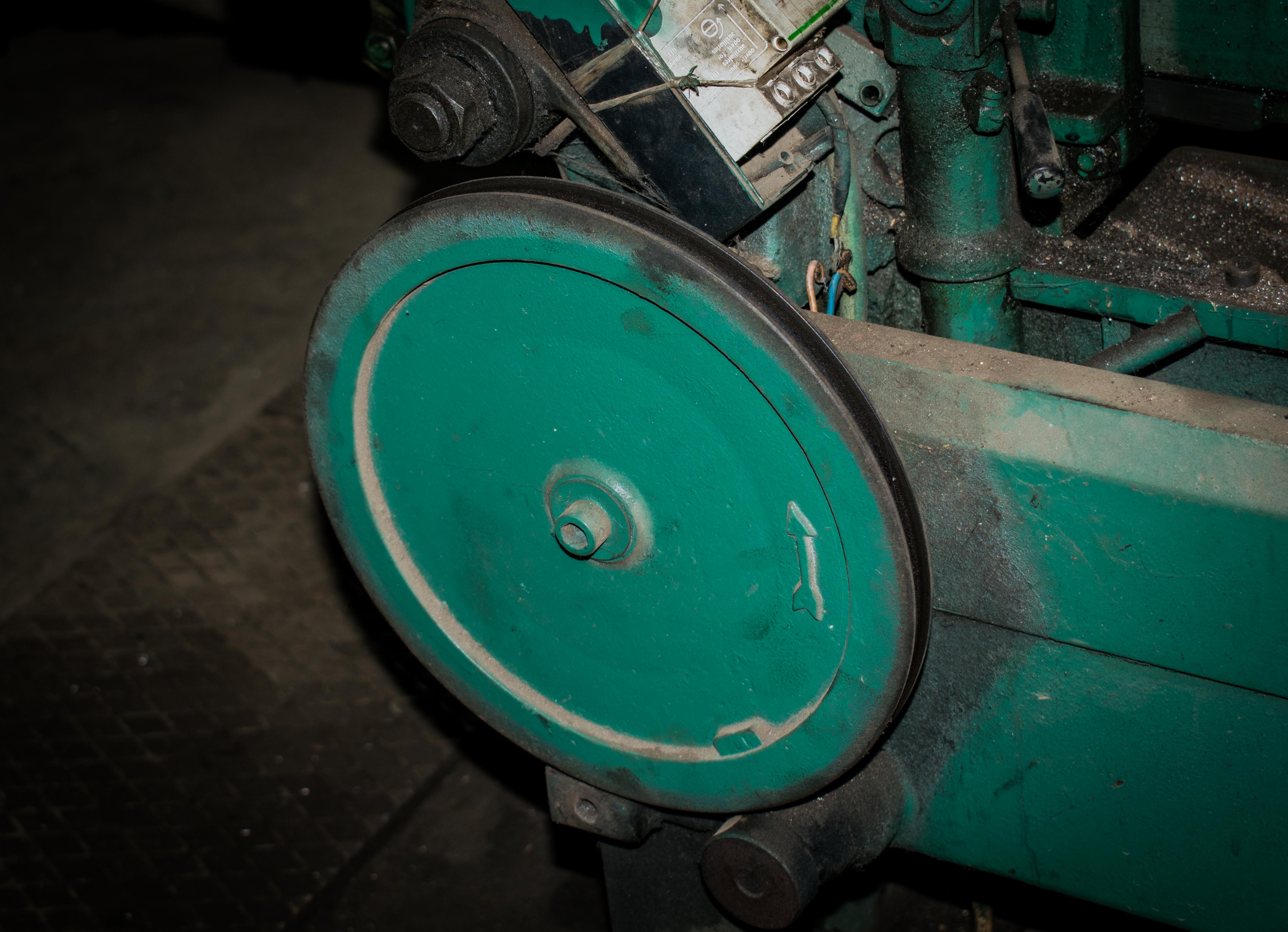
You may have already started to wonder what this does… It is a flywheel designed to do what is called ‘supporting rotation’ in engineering. It moves to and fro with the saw arm helping to support the motion in each direction. The arrow on it indicates the first movement direction of the saw arm.
The base/Support
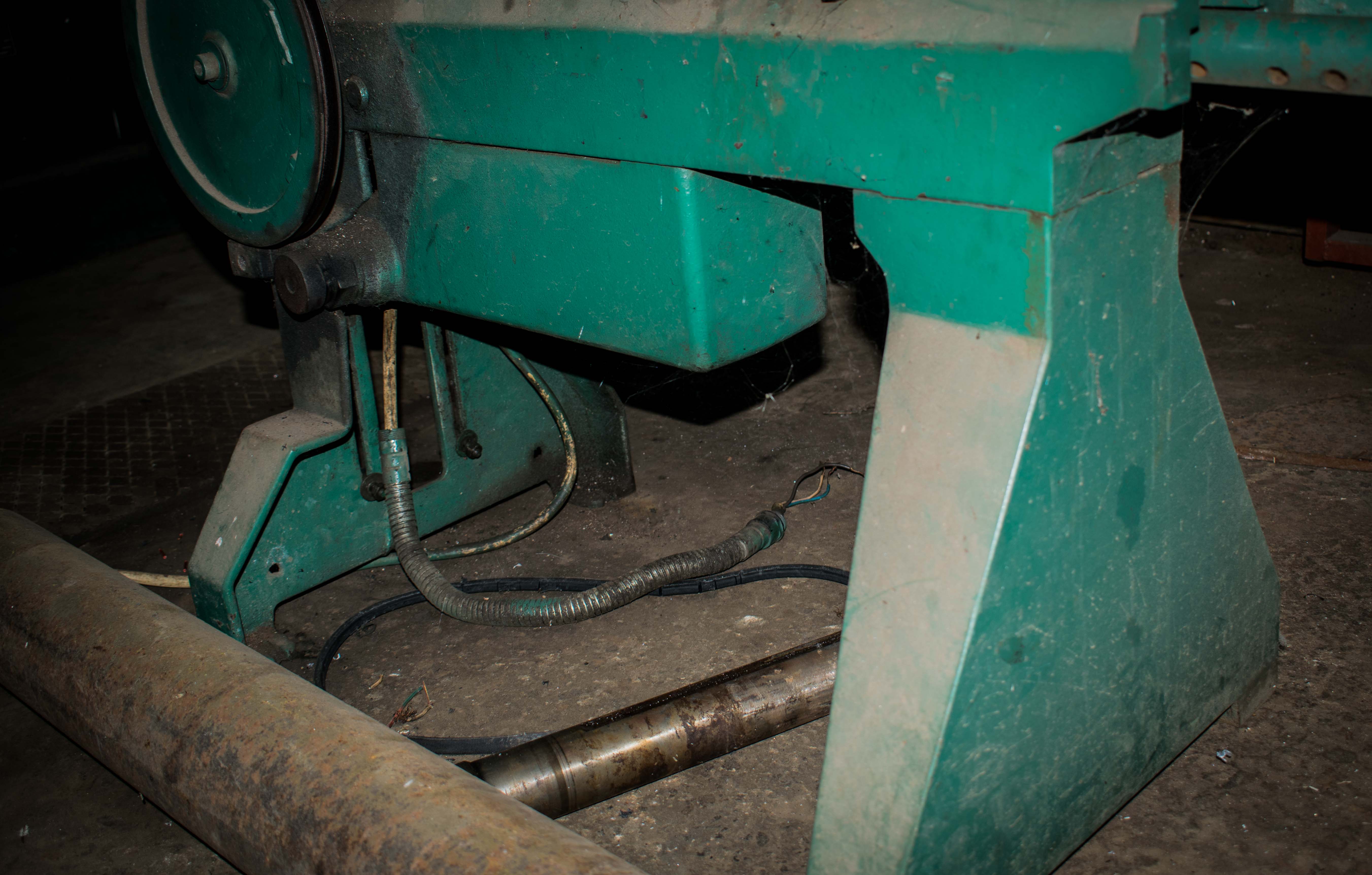
Off course, for a machine that almost rocks during operation, a firm base is needed. The base is designed with steel and is heavier than the whole mechanism on top of it. The base is the power saw carrier.
The next time you see a power saw, I guess you can identify the parts pretty well.
All images are my original works.
Tell me if this was educating. Thanks.
Here are some previous post I also did on ‘Engineering photography'...
HOW TO CHARGE YOUR DC AUTOMOBILE BATTERY!
https://steemit.com/science/@omonosa/how-to-charge-your-dc-automobile-battery-explained-with-images
CONNECTING A LAMP-HOLDER EXPLAINED WITH IMAGES!
https://steemit.com/steemiteducation/@omonosa/connecting-a-lamp-holder-explained-with-image.
cheers!
Thanks to you i can identify the components of a power saw. Love your posts on Engineering Photography,you give detailed explanation with beautiful photographs.
I'm glad @druids! I always try as much as possible to make them easy to take in. People tag tech as being boring. I think a little bit of photography in it adds some little spice.
Another amazing and educating post from you @omonosa.
The pictures and the detailed explanation of the different parts of this machine and the role they play towards making work easier are just so on point.
The power saw is a beautiful piece, carefully and thoroughly designed.
Thanks @dyz7. Its a good thing you took out time to read through.
See no reason going to Google to learn on power saw when I can come here and learn effectively, nice write up @omonosa ,indeed its educating,informative and interesting.
Thanks @hboi.
These post is fascinating!
The images.....on point!👌
Now if these kind of information was added to the theories we are bombarded with in school, we would have been great Engineers already that the world seeks.
I love how you described the rotation relation between the gears. Another thing worth noting is that because the driven gear is much larger than the driving gear, the machine provides greater torque at the detriment of speed. This is a good thing as torque is what is required and not speed.
The dead weight is simple but innovative, I swear down. It reminds me of how we press down a hand saw when we apply an oscillating force on it. The dead weight is a representation of this "hand" and it also provides dynamic balancing.
Awesome one sir!
Respect!
I wish steemit made provisions for bookmarking posts, this would have been bookmarked already!
Cheers!😎
Thanks alot @ced000 for your contribution. It is on point!
I want people to see that technology can become very interesting with good and detailed images!
Lol.. bookmark!
Doing an excellent Job @ it already!😏
Wonderful post, so detailed, so graphical. Explains the power saw with simplicity. Great job