Basic working of diode: A simple circuit and simulation analysis.
Assalamu alaikum Everyone. I am @imranhassan From #Bangladesh
.png)
In the world of electronics, a diode is a basic component that helps the current to flow in a specific direction. I have tried to explain the real picture of the anode–cathode, forward bias, and current flow of a diode through voltage-current analysis. This circuit will serve as an effective practice for beginners to understand diodes, so let's start step by step.
| Parts used and their functions |
|---|
| Parts | Value | Function |
|---|---|---|
| DC Voltage Source | ≈12.8 V | Power supply to the circuit |
| Diode | Silicon Diode | Ensures one-way current flow |
| Resistor | 1 kΩ | Limits current |
| LED (Green) | — | Output Visually Shows |
| Ground (GND) | 0 V | Reference Voltage |
| Step-based Brief Explanation |
|---|
Step -01:
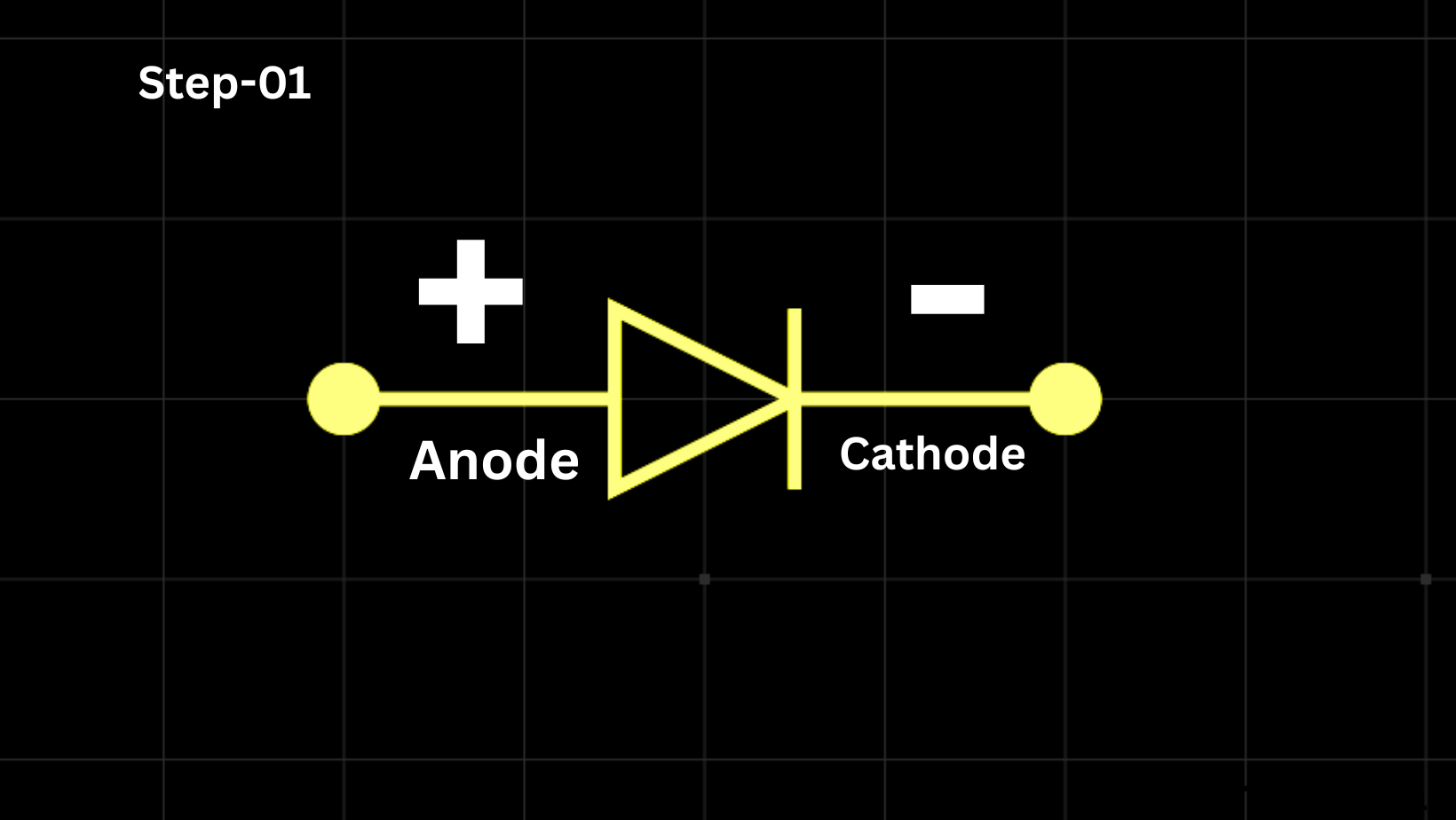
Here you can see that I have determined the symbol and anode–cathode direction of the diode through the simulation software so that the correct direction of the current can be understood. And when I complete the circuit, so that its explanation can be understood very well.
Step -02:
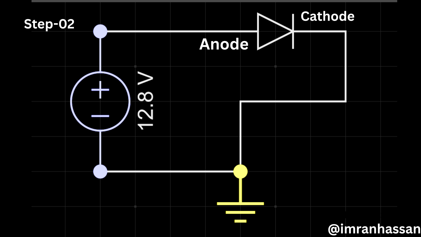
Now you can see that I have added a 12-volt DC voltage source on the left side of the hand; the diode has been brought into forward bias.
Step -03:
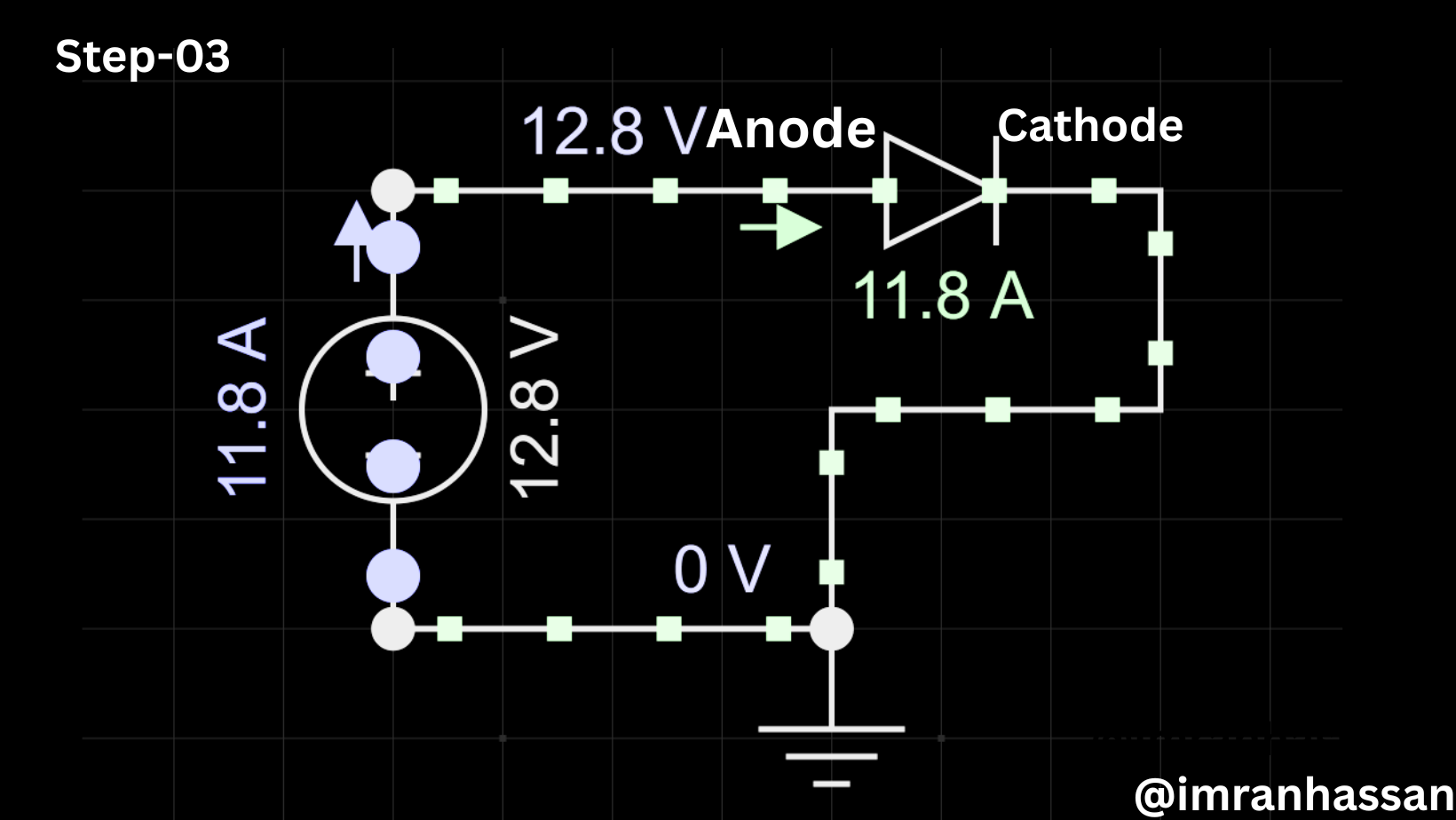
And you can see that after turning on the simulation, some round dots are flowing on one side of the diode, and another symbol is given.
Step -04:
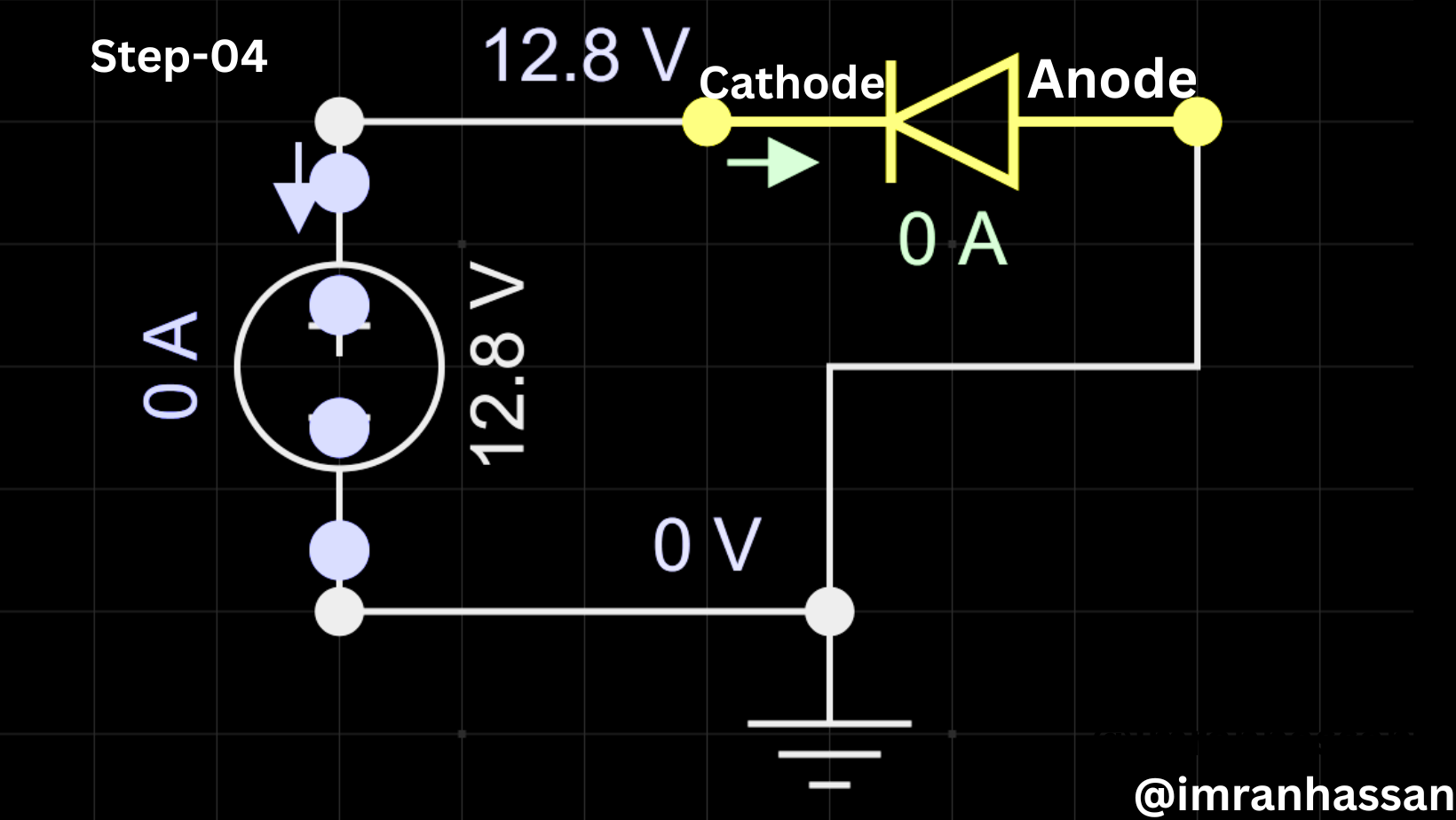
Now you can see that I have completed the circuit, but I have reversed the diode, and you can see that if I reverse the diode, what can be the problem, and how can it stop the current flowing? I am showing you now. Here you can see that the round dots have reached the diode and are stuck because the circuit is not being completed. To explain this better, I have added an LED here to explain it to you.
Step -05:
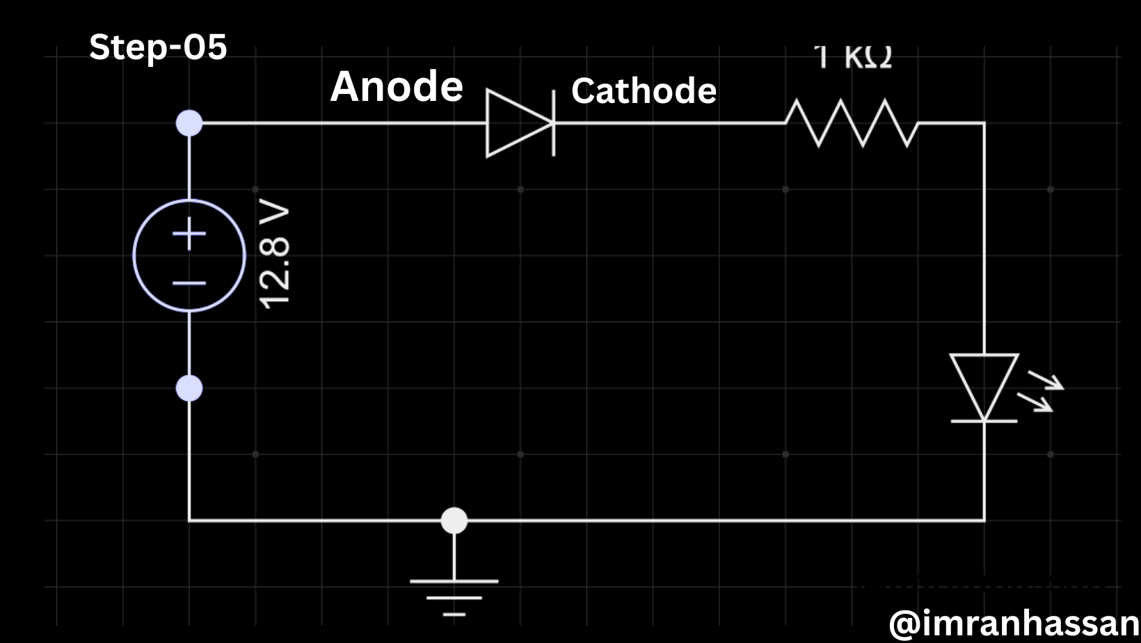
Now you can see that I have made the circuit diagram bigger and added a resistor along with the diode and also added an LED. Since I have a 12-volt power supply here, my LED will cut off, so I have used a 1k resistor here so that my LED is good.
Step -06:
Now you can see that I have connected here, but I have reversed the diode and started the circuit simulation, and you can see that the LED is not lighting up because the diode is blocking the current. And the round dots are stopping at the diode, which we understand as current. So let's turn the diode symbol back and replace it correctly and complete the circuit.
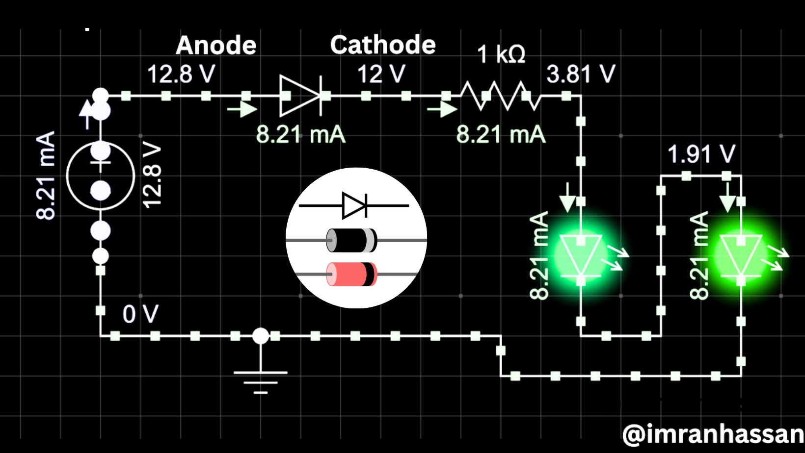
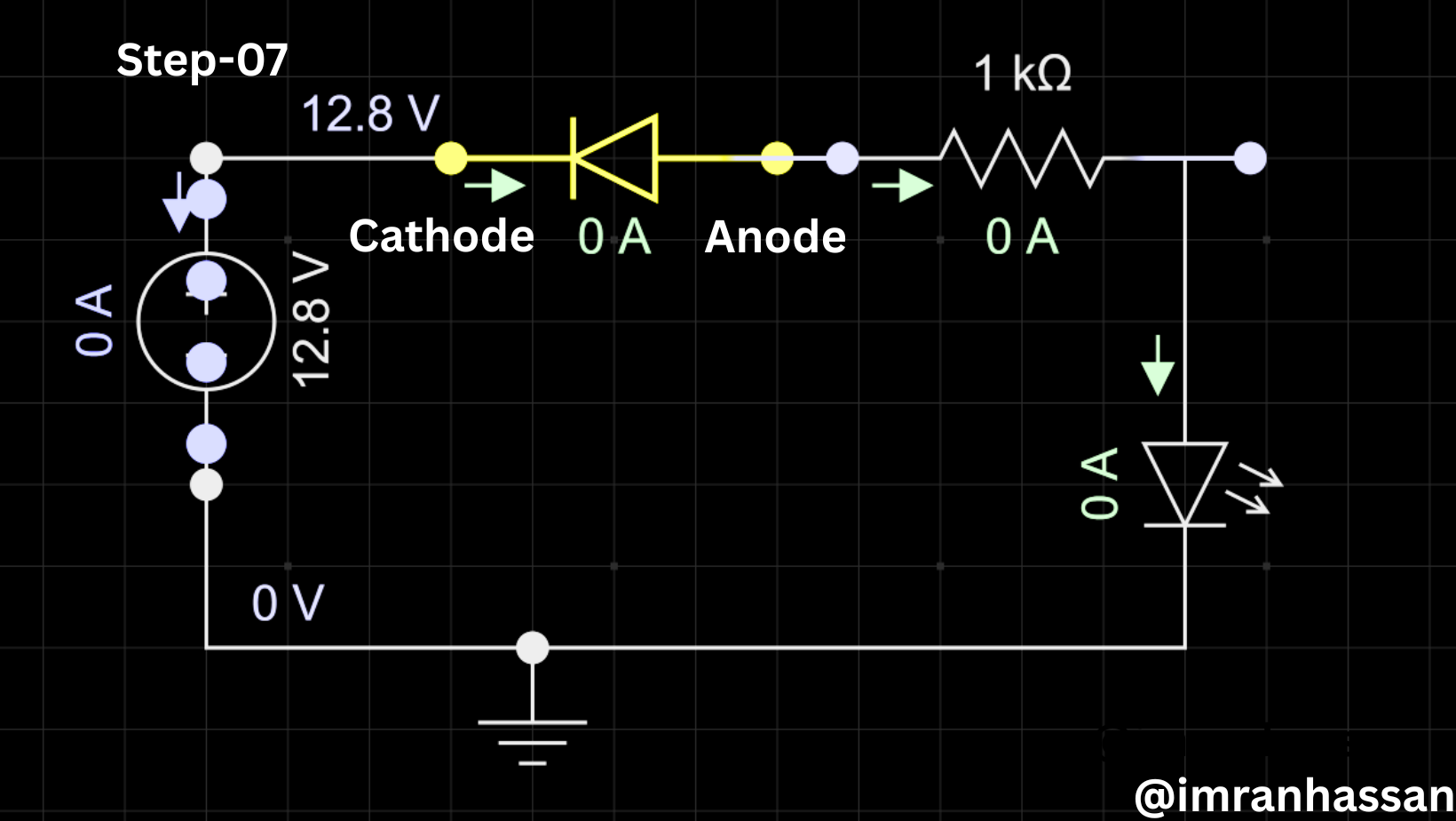
Step -07:
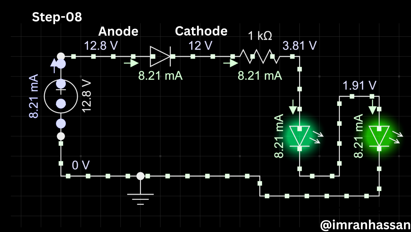
Now you can see that I have replaced the diode symbol here correctly and added two LEDs in a series line, and you can see that my LEDs are running through 1k resistance, and we know that diodes allow current to flow in one direction and block it in the other direction. This is what we want to explain here.
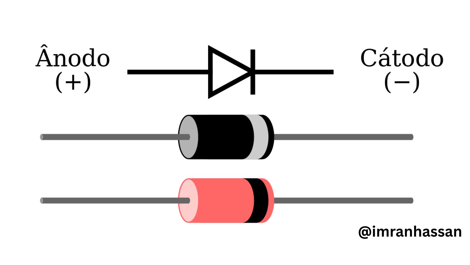
| To better understand the diode symbol, here is a real and a symbolic image. |
|---|
 |
|---|

At one time I also used to see these parts in the circuit, but I didn't know what they did, but at that time, out of curiosity, I used to say that they are inside the amulet circuit. But at one time when I slowly understood everything about the diode, resistor, inductor, and capacitor, I analysed everything.

✅ CC: My friend @rmm31
✅ We support @pennsif and @pennsif.witness for the growth of this platform. pennsif.witness his contribution to the Steemit community. Vote for him as a Witness here: Click to Vote
@emma-uttermost You could publish your electronics-related posts in this community.
@emma-uttermost Yes, of course, if you are an electronics lover, you can connect with me. I had a friend @rmm31 who also posts here. He is from Venezuela. Maybe he is busy now.But you can see my posts in the community. I am unable to post continuously due to my illness and family problems. If the above wishes, my good days will return.However,@sergeyk a great person has given you a mansion to stay connected to my community. I hope you will stay.
Curated by : @ahsansharif
🙏❤️